BE-6910G-HB PROGRAMMABLE ELLIPTICAL STRIDER www.body--sculpture.
INDEX Important Safety Information ………………… 1 Exploded-View Assembly Drawing ……………..….. 2 Parts List 3 …………………………………………….… Assembly Instruction Exercise Instructions …………………………..…… 4-8 …………………..…………..… 9 Trouble Shooting …………………………….
IMPORTANT SAFETY INFORMATION Please keep this manual in a safe place for easy reference. 1. It is important to read this entire manual before assembling and using the equipment. Safe and effective use can only be achieved if the equipment is assembled, maintained and used properly. It is your responsibility to ensure that all users of the equipment are informed of all warnings and precautions. 2.
EXPLODED-VIEW ASSEMBLY DRAWING 2
PARTS LIST FOR BE-6910PGX-HB PART NO. DESCRIPTION QTY PART NO. DESCRIPTION 1. Knob 4 24. 2. Plastic ring 6 25 3. Washer 2 26. Spring washer 2 4. Fixing bolt (M8x20mm) 2 27 Carriage bolt ( M10x90mm) 2 5. Plastic cover (M8) 2 28 Rear stabilizer 1 6. Left pedal post 1 29 Main frame 1 7. Shaft 2 30. Lower cable wire 1 8. Nylock nut (M8) 2 31 Upper cable wire 1 9. Taping screw (ST4.2x19) 4 32 Flat washer(¢10*¢25) 4 10. Taping screw (ST2.
42. Allen wrench (L6) 43. Spanner (13~15~17) 44.
ASSEMBLY INSTRUCTIONS Before beginning remove all contents form the carton and check that all parts are present. Note this may require more than one person. STEP 1 Attach the Front stabilizer (pt.23) to the Main frame (pt.29) using two M10Domed nuts (pt.14), Ø10 Curved washers (pt.13) and two M10x75mm Carriage Bolts (pt.22). Then attch the Rear stabilizer (pt.28) to the Main frame (pt.29) using two M10 Domed nuts (pt.14), Ø10 Curved washers (pt.13) and two M10x90mm Carriage Bolts (pt.27).
STEP 3 Attach the Pedals (L&R)(pt.24&37) to the Pedal post (L&R) (pt.6 & pt.38), using four sets of flat washer ¢10*¢ 25(pt.32),knobs (pt.1), Bolt (pt.25) and then assemble the right and left Pedal post (pt.38 & pt. 6) to the right and left Crank Arm using.Spring washer (pt.26), Plastic ring (pt.2), Washer (pt.3), Spring washer (pt.15) and Fixing bolt M8x20mm (pt.4). Finally, Fit the Plastic cover (pt.5). Repeat the above step for the left pedal. Attach the Right Lower handrail (pt.
STEP 5 Plug the Upper cable wire (pt.31) into the computer cable box at the back of Computer (pt.34), and slide the computer down to the Computer Bracket situated at the top of the Front post (pt.19). Then fix with four Fixing screws M5x10mm (pt.18).
STEP 6 Fit the Inner Handlebar (pt.16) to the Front Post clamp as shown, fix with four Curved washers Ø8 (pt.45), Spring washer Ø8 (pt.15),and four Allen key bolts M8x20mm (pt.21). Plug pulse sensor Wire (pt36) into the computer cable box at the back of Computer (pt.34).
STEP7 please plug the adapter into the socket situated in the rear of the chain cover.
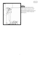
EXERCISE INSTRUCTIONS Using your ELLIPTICAL STRIDER will provide you with several benefits, it will improve your physical fitness, tone muscle and in conjunction with a calorie controlled diet help you lose weight. 1.The Warm-Up Phase This stage helps get the blood flowing around the body and the muscles working properly. It will also reduce the risk of cramp and muscle injury. It is advisable to do a few stretching exercises as shown below. Each stretch should be held for approximately 30 seconds.
3. The Cool Down Phase This stage is to let your Cardio-vascular System and muscles wind down. This is a repeat of the warm up exercise e.g. reduce your tempo, continue for approximately 5 minutes. The stretching exercises should now be repeated, again remembering not to force or jerk your muscles into the stretch. As you get fitter you may need to train longer and harder. It is advisable to train at least three times a week, and if possible space your workouts evenly throughout the week.
Programmable Training Computer - SM3179-67 1.0 Pre-training displays 1.1. Full display (fig.1) [following pedaling or depression of keys] 1.2. Start display (fig.2) [after 1 second] (fig. 1) (fig.2) 1.3. Displays for training mode selection - press UP or DOWN button to select training mode in MANUAL, PROGRAM, USER, TARGET H.R. Press MODE to enter.(fig. 3) (fig. 3) (fig. 4) 1.4. If the training mode selected is Target H.R, the monitor will require an "AGE" input.(fig.
2.0 Displays during training 2.1. Time, Distance, Calories and WATT start counting up from zero when the training starts without function presetting. (fig. 8) 2.2. Before training starts or during training, the profile height could be adjusted (resistance level change) in MANUAL, PROGRAM, and USER training mode. 2.3. If there is any function preset before training, it starts to counting down when the training starts. (fig.9) (fig. 9) (fig. 10) 3.0 Displays when the training is stop 3.
5.0 Heart rate detection priority 5.1. The monitor have three different detection sensors of heart rate: earpulse, chest pulse (with chest belt attached to the chest skin), and handpulse. The detection priority is earpulse, chest pulse, and handpulse. 5.2. When you would like to detect chest pulse, please remove the ear clip cable from the monitor. And, wear on the chest belt to start heart rate detection. 5.3.
RPM Displays current training rotation per minute. SPEED Displays the current SPEED from 0.0 to maximum 99.9 km (or mile) per hour. ** RPM and SPEED will switch display to another in every 6 seconds during training. DISTANCE Count Up - The computer accumulates total workout distance from 0.00 to the max. 99.90 km or ml during training. Count Down - The monitor will count down from the preset to 0.00. CALORIES Count Up- The computer accumulates the calories consumption from 0 to the max.
EXERCISE NOTES Use this space to record your own exercise routine results 16
COPYRIGHT ©2007 BY BODY SCULPTURE INTERNATIONAL EUROPE LTD ALL RIGHTS RESERVED. UNAUTHORIZED DUPLICATION IS A VIOLATION OF LAW.