E738 BodyworX Deluxe Elliptical (Front Drive)
Safety Instructions • To ensure the best safety of the exerciser, regularly check it on damages and worn parts. • If you pass on this exerciser to another person or if you allow another person to use it, make sure that that person is familiar with the content and instructions in these instructions. • Only one person should use the exerciser at a time. • Before the first use and regularly make sure that all screws, bolts and other joints are properly tightened and firmly seated.
• Be sure to set up the exerciser in a dry and even place and always protect it from humidity. If you wish to protect the place particularly against pressure points, contamination, etc., it is recommended to put a suitable, non-slip mat under the exercise • The general rule is that exercisers and training devices are no toys. Therefore, they must only be used by properly informed or instructed persons. •Stop your work-out immediately in case of dizziness, nausea, chest pain or any other physical symptoms.
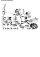
Exploded drawing: 55 53 52R 13 60 40 68 9B 7 6 64 105 54 63 67 65 103 15 68 107 23R 52L 107 23L 12R 76 44 95 106 86 111 75 71 88 51 83 46 70 56 45 50 37 10 41 8 7 9B 69 72 41 60 40 42 72 74A 74B 63 84 73 21 72 102 84 17 14 41 34 49 77 80R 8 21 9B 63 93R 93L 41 8 7 9 6 7 9 43 26 24 12L 57 35 61 16 100 47 89 45 18 94 44 101 19 9A 7 6 22 4 9B 7 8 3 96 1 6 7 9C 32L 80L 32R 102 31 72 107 84 33R 11R 9B 7 6 104R 66 38 33L 104L 63 39 79 5R 81 8 7 20 2 5L
Checking list: 10 12R&L 1 49 X1 64 2 X1 X1 X1 52R&L 3 X1 67&68 X1 19 X2 X1 X1 78 76 11R&L X1 X1 23R&L 74A&B X2 21 X1 18 94 93R&L X1 9 X2 X2 M8*1.25*15L 9A 104R&L X6 X1 X2 X2 X1 60 X8 63 X22 X2 7 D15.4*D8.2*2T X22 D16*D8.5*1.2T X10 M8*1.25*20L X8 8 9C M8*1.25*55L X2 14 17 M10*1.5*10T X2 20 M8*15L X4 75 40 M8*1.25*20L X4 73 M6*1*15L X4 107 41 D24*D10*0.4T X6 77 M6*1.0*5T X4 110 108 D11.5*D8*3.5T 111 M5*15L X2 X2 X1 X2 D22*D8.
Part No. 1 2 3 4 5L 5R 6 7 8 9 9A 9B 9C 10 11L 11R 12L 12R 13 14 15 16 17 17A 18 19 20 21 22 23L 23R 24 25 26 27 28 29 30 31 32L 32R 33 34 35 36L 36R 37 38 39 40 41 42 43 44 45 46 47 48 49 50 51 Description Main frame Front stabilizer Sliding beam Oval cap Left foot cap Right foot cap Curved washer D22*D8.5*1.5T Spring washer D15.4*D8.2*2T Flat washer D16*D8.5*1.2T Allen bolt M8*1.25*15L Allen bolt M8*1.25*95L Allen bolt M8*1.25*20L Allen bolt M8*1.
52L 52R 53 Left movable handlebar Right movable handlebar Foam (HDR) D30*3T*500L Assembly drawing: Step 1 1 1 2 110 111 Bolt M8*1.
(x4) (x2) 81 9A 7 7 D22*D8.5*1.5T 9B 7 M8*1.25*20L (x4) D15.4*D8.2*2T (x4) (x2) (x2) 20 7 8 1 20 7 8 9B 7 6 2 81 81 19 (A) 9A 7 6 19 3 8 7 9B 6 94 18 7 9C 1 1) Assemble the sliding beam (3) to the rear stabilizer (19) by the Allen bolt (9A), the Allen bolt (9B), the curved washer (6), the spring washer (7) and the flat washer (8). 2) Assemble the connecting tube (18) to the sliding beam (3) by the Allen bolt (9C), the curved washer (6) and the spring washer (7).
Step 2 (x4) 9 M8*1.25*15L 7 D15.4*D8.2*2T (A) (x2) 9 M8*1.25*15L 7 D15.4*D8.2*2T 10 49 30 8 7 9 29 6 7 9 (B) 29 30 22 2 1) Assemble the handlebar post cover (49) to the handlebar post (10) shown as fig. A. 2) Connect the upper computer cable (29) and the lower computer cable (30) shown as fig. B. 3) Assemble the handlebar post (10) to the main frame (1) by the curved washer (6), the spring washer (7), the flat washer (8) and the Allen bolt (9).
Step 3 (x2) 40 M8*1.25*20L 60 75 52R 52L 3-1 60 40 10 23R 75 52L x2 3 Assemble the upper cover (right) (23R), the waved washer (75), the movable handlebar (52L&52R), the flat washer (60) and the bolt (40) to the axle in turn shown as fig. 3-1.
Step 4 (x2) (x4) M10*1.5*10T M6*1*15L M6*1.0*5T (x4) 110 60 D25*D8.5*2.0T 108 D11.5*D8*3.5T 38 66 110 109 110 60 108 21 73 77 4-2 4-1 17 14 41 11L x2 74B 11L 41 31 74A x2 63 4 1) Assemble the supporting tube for pedal (11L&11R) to the rolling axle (31) by the Nylon nut (17), the flat washer (14) and the plastic flat washer (41) shown as fig. 4-1.
Step 5 M8*1.25*20L (x2) (x2) (x6) (x2) 12R 12L 32L 5-2 5-1 12L 107 104R 84 63 32L 72 60 40 104L 41 x2 x2 5 1) Assemble the supporting tube for movable handlebar (12L&12R) to the bracket for pedal (32L&32R) by the waved washer (84), the bushing (72), the flat washer (60) and the bolt (40) shown as fig. 5-1. 2) Assemble the cover for universal joint (104L&104R) to the bracket for pedal (32L&32R) by the screw (63) and the screw (107).
Step 6 105 64 64 65 29 6 (x16) ST4*15L 10 6-1 52R 52L 9B 7 6 x2 52L 12L 6-2 52L 63 23R 23L x2 6-3 63 6 93R x2 11L 3 93L 1) Connect the upper computer cable (29) and the handle pulse cable (65) to the computer (64). 2) Assemble the computer (64) to the handlebar post (10) by screws that attach to the computer.
Step 7 63 (x2) ST4*15L 107 (x2) 63 67 111 (x2) 107 68 10 107 M5*15L M5*15L 106 111 76 7 78 1) Assemble the left computer bracket (68) and the right computer bracket (67) to the handlebar post (10) by the screw (63) and the screw (107). 2) Assemble the bottle holder (106) to the handlebar post (10) by the screw (111). Assemble the bottle (76) to the bottle holder (106). 3) Assemble the adaptor (78) and turn on the computer.
Computer B31232: The things you should know before exercise A. Input Power Plug in the adaptor to the equipment then the computer will produce a beep sound and turn on the computer at the Manual mode. B. Program select and setting value 1. Use the UP or DOWN keys to select program mode and then press ENTER to confirm your exercise mode. 2. At the Manual mode, the computer will use the UP or DOWN keys to set up your exercise TIME, DISTANCE, CALORIES, PULSE. 3. Press the START/STOP key to start exercise. 4.
Program Introduction & Operation: Manual Program: Manual P1 is a manual program. User can start exercise by pressing START/STOP key. The default resistance level is 5. Users may exercise in any desirous of resistance level (Adjusting by UP/DOWN keys during the workout) with a period of time or a number of calories or a certain distance. Operations: 1. Use UP/DOWN keys to select the MANUAL (P1) program. 2. Press the ENTER key to enter MANUAL program. 3.
Program 20 is the 75% Max H.R.C. - - Target H.R. = (220 – AGE) x 75% Program 21 is the 85% Max H.R.C. - - Target H.R. = (220 – AGE) x 85% Program 22 is the Target H.R.C. - - Workout by your target heart rate value. Users can exercise according to your desired Heart Rate program by setting your AGE, TIME, DISTANCE, CALORIES or TARGET PULSE. In these programs, the computer will adjust the resistance level according to the heart rate detected.
6. The AGE will flash and you can press UP or DOWN keys to set your AGE. Press ENTER key to confirm your AGE. The default AGE is 35. 7. Press the START/STOP key to begin body fat measurement. If the window show E on the window, please make sure your hands are attached well on the grips or the chest belt is touch well on your body. Then press the START/STOP key again to begin body fat measurement. 8.
PROGRAM 7 (RAMP): PROGRAM 8 (MOUNTAIN): PROGRAM 9 (INTERVALS): PROGRAM 10 (RANDOM): PROGRAM 11 (PLATEAU): PROGRAM 12 (FARTLEK): PROGRAM 13 (PRECIPICE): PROGRAM 14 (USER-1 PROFILE) PROGRAM 15 (USER-2 PROFILE) PROGRAM 16 (USER-3 PROFILE) PROGRAM 17 (USER-4 PROFILE) PROGRAM 18 (55% H.R.C): PROGRAM 19 (65% H.R.
PROGRAM 20 (75% H.R.C): PROGRAM 21 (85% H.R.C): PROGRAM 22 (target H.R.C): PROGRAM 24 PROGRAM 23 (WATT): (BODY FAT ): Remark : USER 1 – 4, HRC 55% - 85% , THRC , WATT CONTROL --- AFTER START TO CHANGE PROFILE AS BELOW.