Boekel MicroCooler II Models 260010 and 260010-2 Operating Instructions N2400150 Rev.
CONTENTS 1. 2. 3. 3.1 3.2 4. 4.1 4.2 4.3 4.4 5. 5.1 5.2 6. 7. 8. 8.1 8.2 9. 10. Page Safety .............................................................................................................................. 2 Product Information ........................................................................................................ 3 Assembly......................................................................................................................... 3 Unpacking .....................
1. Safety The following symbols marked on the equipment mean: Caution: Read these operating instructions fully before use and pay particular attention to sections containing this symbol. Attention: Suivre attentivement les instructions avant l’usage et prêtez une attention particulière aux sections comportant ce symbole. Always observe the following safety precautions: • • • • • • • • • • • • • Use only as specified by the operating instructions or the intrinsic protection may be impaired.
2. Product Information The Boekel MicroCooler II cold well incubator is a compact and convenient alternative to expensive and bulky refrigerated water baths. The MicroCooler II is an ideal way for labs to incubate or store samples at temperatures from ambient down to 18°C below ambient, typically 4°C.
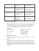
4. 4.1 Operation Controls and Displays 2. Cooling Indicator LED 1. Power key 3. Temperature Display 4. Set function key 5. Up and Down arrow keys 1. Power Key ( ) – Controls Power to the unit 2. Cooling Indicator Light-Green LED indicated cooling Function 3. Temperature Display- Displays the current well temperature of the unit. 4. Set (S) function Key- is used to adjust the temperature of the unit 5. Up () and Down () arrow keys-are used to adjust the set temperature 4.
will begin cooling to the set temperature. The Green Cooling indicator LED will indicate the Cooling Function. A blinking indicator LED shows that the system is nearing the temperature set point and will stabilize to the set temperature. 4.4 Operating the MicroCooler II The MicroCooler II is rated to work at temperatures between ambient and 18°C below ambient, typically 4°C.
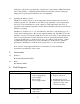
3. Well temperature continues to rise when not expected 4. Well temperature does not cool when expected to 5. Well temperature continues to cool when not expected 7. b. Temperature control circuit fault b. Have unit checked by competent person a. Actual temperature is lower than set temperature b. Temperature control circuit fault a. Check set temperature a. Actual temperature is lower than set temperature b. Temperature control circuit fault a. Check set temperature a.
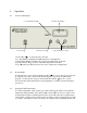
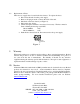
.2 Replacement of Fuses There are two supply fuses located in the fuse drawer. To replace the fuses: • Disconnect the unit from the power supply. • Remove the plug from the socket in the back of the unit. • Pull back on the fuse drawer (see Figure 2). • Pull out the fuse drawer. • Check and replace with the correct fuses if necessary. The fuses must be 5mm x 20mm quick acting, rated 250V. Model 260010: 2AF Model 260010-2: 1AF • Push the fuse drawer back in. Reconnect unit to the power supply.
website: www.boekelsci.