EPN-5131 Gravity Latch Installation Instructions • English ........................................................ 1 • Français ...................................................... 6 • Español ....................................................... 11 Read all instructions prior to installing product. Refer to manufacturers safety instructions when operating any tools. To register your product, please visit: boerboelgatesystems.
WARNING: • Improper installation of this product can result in personal injury. Always wear safety goggles when cutting, drilling and assembling the product. • Incorrect installation may cause harm to the gate or individual. • Not pool code approved. NOTICE: • DO NOT attempt to assemble the kit if parts are missing or damaged. • DO NOT return the product to the store, for assistance or replacement parts call: 1-800-336-2383.
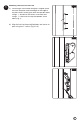
1 Mounting The Latch To The Post Fig. 1 a.) Once hinges are installed and gate is aligned, place the latch template at desired height at the edge of the post closest to the gate. Mark and pre-drill holes using a 5⁄8" drill bit for the center screw hole and using a 3⁄32" drill bit for the top and bottom screw holes (Fig. 1). Post Drill 3/32" Template Drill 5/8" b.) Align the latch to the pre-drilled holes and secure to post using two 1" screws (Fig. 2 & 3). Drill 3/32" Fig. 2 Post Latch Fig.
2 Mounting The Striker To The Gate Upright Fig. 4 a.) Align the striker along the edge of the gate upright, in the closed position with the latch. Mark the two holes on the front of the striker (Fig. 4). b.) Mark the third hole on the side of the striker, and pre-drill all three holes of the striker using a 3⁄32" drill bit (Fig 5.) c.) Secure striker to gate using three 1" screws (Fig. 6). Fig. 5 Mark and Pre-drill Fig.
Limited Lifetime Warranty Subject to the conditions and limitations set out below, Barrette Outdoor Living warrants that for so long as the original purchaser of a product manufactured by Barrette Outdoor Living owns that Boerboel Manual Hardware (the Product) it will be free from all defects due to faulty design, materials or workmanship.
Loquet à pesanteur Instruction d’installation • English ........................................................ 1 • Français ...................................................... 6 • Español ....................................................... 11 Lire toutes les instructions avant d’installer le produit. Consulter les consignes de sécurité du fabricant lors de l’utilisation des outils. Pour enregistrer votre produit, veuillez visiter : boerboelgatesystems.
AVERTISSEMENT : • L’installation incorrecte de ce produit peut entraîner des blessures. On doit toujours porter des lunettes de sécurité lors de la coupe, du perçage et de l’assemblage du produit. • Une installation incorrecte est susceptible de causer des dommages à la barrière ou des blessures à la personne qui fait l’installation. • Ce produit n’est pas approuvé pour les piscines.
1 Montage du loquet sur le poteau a) Une fois que les charnières sont installées et que la barrière est bien alignée, placer le gabarit de loquet à la hauteur désirée sur le bord du poteau le plus près de la barrière. Après avoir marqué l’emplacement des avant-trous, percer les avanttrous au moyen d’un foret de 16 mm pour le trou du centre et d’un foret de 2,38 mm pour les trous du bas et du haut (Fig. 1). Fig.
2 Montage de la gâche sur le montant de barrière Fig. 4 a) Aligner la gâche sur le loquet en position fermée le long du bord du montant de barrière. Marquer l’emplacement des deux trous à l’avant de la gâche (Fig. 4). b) Marquer l’emplacement du troisième trou sur le côté de la gâche ; puis, percer les trois avant-trous pour la gâche au moyen d’un foret de 2,38 mm (Fig. 5). c) Fixer la gâche à la barrière à l’aide de trois vis de 25 mm (Fig. 6). Fig. 5 Marquer et percer les avant-trous Fig.
Garantie limitée à vie Sous réserve des conditions et restrictions énoncées ci-dessous, Barrette Outdoor Living garantit que, pour aussi longtemps que l'acheteur initial d'un produit fabriqué par Barrette Outdoor Living possède le « Boerboel Manuel Hardware » (le produit), celuici sera exempt de toutes défectuosités dues à la conception, aux matériaux ou à une mauvaise fabrication.
Cerrojo de gravedad Instrucciones de instalación • English ........................................................ 1 • Français ...................................................... 6 • Español ....................................................... 11 Lea todas las instrucciones antes de instalar el producto. Consulte las instrucciones de seguridad del fabricante al utilizar herramientas. Para registrar su producto, visite: boerboelgatesystems.
ADVERTENCIA: • La instalación incorrecta de este producto puede provocar lesiones corporales. Utilice siempre gafas de seguridad al cortar, taladrar y ensamblar el producto. • La instalación incorrecta puede causar daños a la puerta o a personas. • No aprobado por el código de piscinas. AVISO: • No intente instalar el kit si faltan piezas o las piezas están dañadas. • no devuelva el producto a la tienda; para solicitar ayuda o piezas de repuesto llame al: 1-800-336-2383.
1 Instalar el cerrojo en el poste a.) Una vez que se hayan instalado las bisagras y la puerta esté alineada, coloque la plantilla del cerrojo a la altura deseada en el borde del poste más cercano a la puerta. Marque y taladre los agujeros con una broca de 5⁄8" para el agujeros central y una broca de 3⁄32" para los agujeros superior e inferior (Fig. 1). Fig. 1 Poste Broca de 3/32" Plantilla Broca de 5/8" b.) Alinee el cerrojo con los agujeros perforados y fije al poste usando dos tornillos de 1" (Fig.
2 Instalar la traba en el soporte vertical de puerta Fig. 4 a.) Alinee la traba con el borde del soporte vertical de puerta, con el cerrojo en posición de cerrado. Marque los dos agujeros en la parte delantera de la traba (Fig. 4). b.) Marque el tercer agujero en el costado de la traba, y taladre los tres agujeros de la traba con una broca de 3⁄32" (Fig 5.) c.) FIje la traba en la puerta con tres tornillos de 1" (Fig. 6) Fig. 5 Marque y perfore Fig.
Garantía limitada de por vida Sujeto a las condiciones y limitaciones establecidas a continuación, Barrette Outdoor Living garantiza que siempre que el comprador original de un producto fabricado por Barrette Outdoor Living sea propietario de Boerboel Manual Hardware (el Producto) este estará libre de todo defecto debido a defectos en el diseño, materiales o mano de obra.
BARRETTE OUTDOOR LIVING 7830 FREEWAY CIRCLE MIDDLEBURG HEIGHTS, OHIO 44130 TEL: (800) 336-2383 WWW.BOERBOELGATESYSTEMS.