
TM-2030 Installation & User Guide
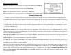

Turn off main breaker to battery before attempting installation. Remove all connections from battery negative post.
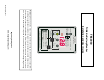
A. 4-Wire cable. Most multi-conductor cable is suitable for this application. Cable jacket (outer casing) should be removed to avoid contact
with battery, shunt connections or other heat sources.
If installed near high current carrying wires for 10 feet or more: Use twisted pair. “G2” and “SIG” should be run with one twisted
pair, and if another pair is used, “G1” and “+B1” may be paired. CAT5 may be used for long runs up to 350 ft. Visit our support
page at www.bogartengineering.com for more information.
B. B1 wire 1-amp fast-blow glass fuse required. Do not insert the fuse into the fuse-holder until installation is complete
C. Optional B2 wire connects to vehicle (starting) battery or 2nd battery bank to measure voltage only.
D. Battery Cable. Length from 6 inches to several feet as necessary. Battery cable must be large enough to accommodate maxi-
mum amps going to and from battery. This is the only connection to the battery negative post unless a temperature sensor is
used.
E. SIG wire (white). Must connect to the small kelvin terminal on the “battery side” of the shunt.
F. Load side of Shunt. Negative WIRES from ALL charging sources and loads CONNECT HERE TO MEASURE CURRENT
including SOLAR PANELS, CHARGE CONTROLLER, ALTERNATOR, INVERTER, AND CHASSIS GROUND (IF APPLICA-
BLE). Okay to use bus bar as long as connection is ultimately to the shunt. Note: The shunt measures all current to be dis-
played by the meter.
G. G1 and G2 wires (black) connect together at small kelvin terminal on “load side” of shunt.
H. Phone connector for crossover type modular cable to connect meter to SC-2030 Solar Charge Controller (if used). May
also be used for serial data connection.
Visit www.bogartengineering.com/support for more information
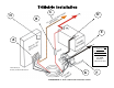
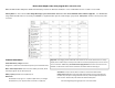
TRIMETRICINSTALLATION:
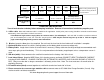
Wire Length
(feet)
45 70 110 150 300 Over 300
Wire Gauge # 26 # 24 # 22 # 20 # 18 CAT5
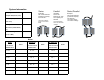
Shunt Type
500 Amp-50 mV (default)
“H” under P11
100 Amp-100mV
Set to “L” under P11
1000 Amp-100mV
(rarely used) “H” under P11
Maximum Charging
Amps
400 75 650
Refertohp://www.nfpa.org
forelectricalwiringstandards
andinformaon