TriMetric TM-2030 Battery system monitor, Models TM-2030-RV and TM-2030-A Technical Manual INSTALLATION Page 1-7 USER GUIDE Page 8-23 revised June 2017 IMPORTANT: The wiring installation for this meter, especially the shunt installation must be performed by someone knowledgeable in proper wiring, electrical practices, and safety. If you do not have this knowledge please have someone install it who does, or at least get some competent help to supervise the installation. To install: 1.
A: What you may need to know before installing the TriMetric meter. Review this (briefly) before installing. The TriMetric is usually located in the living area where people using the power can readily observe it. It is usually located less than 100 ft from batteries. For greater distances refer to section B2 for details. If the optional SC-2030 Solar charger is also to be used, the charger is typically located near the batteries where it can be completely controlled from the TriMetric TM-2030.
B. How to Install METER and SHUNT B.1. Preliminary •IMPORTANT: A qualified person familiar with safe electrical practices and the local electrical code should install this meter--particularly when installing the shunt. Accidentally shorting the battery with a tool or other metal such as a finger ring can result in severe burns from an arc. Mistakes in wiring could seriously damage your electrical system. •Refer to wiring drawing on last page--please read all notes.
If your system has four 6V batteries in series-parallel, or two 12V batteries in parallel, then on the negative side of the battery system you will then have only one cable connecting two negative poles from two different batteries connected together. Before step 2, there must be no other wires going to inverters, grounds, solar controllers or ANYTHING ELSE connected to the negative side of the battery system except for one cable that connects the two battery negative poles together.
b. Then connect the SIG wire to the other Kelvin “battery side” terminal (closest to the minus battery connection.) c. Connect the wire for the +B1 connection to one side of the one amp fuse holder. Don’t yet put in the fuse. d. A wire from the other side of the fuse holder must connect to the + terminal of the main battery set. We suggest connecting it directly to the + battery terminals so that the meter will operate even if a main breaker is turned off. e.
5. As before, momentarily push both SELECT and RESET—three green lights will flash. Enter your “battery capacity” in amp hours. If you do not know what your “battery capacity” is, see below “How to determine battery system capacity. As before, the RESET button will increase the numbers. Note that the display can’t show above 999, so above this you will see a flashing decimal point. The flashing decimal point means “multiply the number by 1000.” .
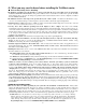
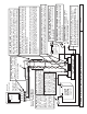
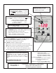
TM-2030 Magnified view of 5 TERMINAL STRIP located on circuit board. SIG G2 G1 B1+ FIGURE 2: TM-2030 TriMetric Battery Monitor Connections Measure volts, amps, % full. G2 G1 B1+ G1 SHUNT: 50 MV/500 AMP OR 100 MV/100 AMP IMPORTANT: Be sure this side of shunt is connected to nothing but negative terminal(s) of the battery set that you want to monitor the "amps". Otherwise your meter amps will not be correct. (If 2nd battery is used, with only volts measured, connect as shown at right.
USER GUIDE 1. Overview of TM-2030-RV or TM2030-A battery system monitor 2. Basic instructions for Operating Level L1 2.1 More details on the five less used display items 2.2 What are Battery Reminders? 2.
1. Overview of TM-2030-RV and TM-2030-A battery system monitor The TM 2030 is intended to keep you informed about 12V to 48V battery systems, such as ones found in RV’s or off grid homes—which are regularly charged and discharged and use “deep cycle” batteries. The TM2030 may also be used with the new, optional Bogart Engineering SC-2030 30 amp solar charger. These two will together allow both flexible and accurate solar charging and comprehensive monitoring of batteries.
IMPORTANT DISPLAY NOTE: Flashing decimal point means “multiply the number seen by 1000” CHARGING LIGHT: When lighted shows “battery 1 is charging” (“amps” or “watts” is positive) Flashing lamp means battery is charged. TM 2030-RV BATTERY REMINDERS: (optional) Lamp flashes and display occasionally shows these letters when: battery should be recharged “Ch.F” or “battery should be equalized” “Ch.E” or “battery voltage low” “b.
dSC Shows the number of days since the battery has been fully charged. This display gradually increases by 1.00 every day until the battery is charged, at which time this value is automatically reset to 0.00. To understand precisely what the TriMetric considers “charged”, refer to section 6.2: How the TriMetric keeps track of Battery%Full. For this number to be correct, Program values P1, P2 and P3 must be correct as described in “Installer’s Instructions for TriMetric TM-2030.
3. Beyond beginners: Instructions for Operating levels L2, L3, L4. To change: see Table 2, program P7. Level L2 has all the functions of L1, but also allows access to some history information (see below) intended to help technicians in analyzing systems to see that they are operating properly. Section 4 has a brief description. Section 6.3 has more details. Level L3 and L4 have all functions of L2, and also adds additional programming functions summarized in Table 3 and detailed in section 2.3 and 6.4.
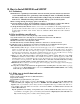
5. Summary of Programming instructions Program functions applicable for Operating Level L1 are summarized in Table 2 below. As mentioned above, it is most important that items P1, P2 and P3 (below in Table 1) be correctly programmed for the Battery%Full data to be correct. A step by step procedure for doing this is described in the “Installer’s Instructions for TriMetric 2030. The additional functions applicable to level L3 are summarized in Table 3 below.
PROGRAM MODE NUMBER *Used by PROGRAMMABLE DATA and ADJUSTMENT RANGE Factory (and L1,L2) value. WHAT IT IS FOR (SUMMARY) Where to find more information. write your value here SC-2030 charger *P8 Max Allowed Charger Voltage 10.0-65.
6. Reference section: more technical information: 6.1 TM-2030 Specifications Main battery (B1): Measures Volts, Amps, Watts, Battery % Full, Amp-hours from full, Days since charged, Timer for days since Equalized. Also data logging (history data) described below. Secondary Battery (B2) sharing common negative with main battery: Measures volts only Battery Volts: From 10.0 – 65.0 volts for main battery. From 0.0 to 100 volts on secondary battery. Resolution 0.1 volt. Accuracy ± 0.
batteries must reach the “float” condition as described in the “SC-2030 Solar Charge Controller User’s Manual” section 6.5. 2. When the above occurs, the TriMetric then declares the battery “charged” by flashing the “charging” light and resets the “Days since charged” to 0. 3.When the charging is completed, and the batteries start to discharge again the “Amp hours from full” display is reset to 0.00, and Battery%Full is reset to 100%.
would cost twice as much to replace. (Of course you’d get more days of autonomy.) But in a vehicle it would add extra weight. This measurement is a way of getting quantitative data on these kinds of questions. H2-H6: Battery Charge Cycle Data provide answers to these system questions for the last five charge/discharge cycles: A discharge/charge cycle begins at the time the battery is “fully charged” and ends at the next “full charge”—a precise definition is given in section 6.
●Each recorded data represents a 24 hour period that ends at a time of day (or night) that you can determine by referring to Program 17, on page 13 Purpose of H7, H8 data: The way that the TriMetric determines that the batteries are “charged” (in Level 1, 2 and 3 operation) is to sense that the battery volts exceeded the programmed P1 value, and the charging Amps are less than the value of P2 times P3 (P2 is expressed as a percentage).
you must know the amp-hour capacity of your battery system which has been set in program P3. We often suggest value for the “current setpoint” setting that is 2% of C, which is the default setting when the meter is new, where C=battery system capacity in amp-hours that is programmed in P3. For example if you put =700 amp hours into P3, then a P2 amps setting of 2% would be 2% of 700 = 14 amps. Better charging would result using 1% of C or even 0.
P12: Automatic reset on/off for amp hours described in section 6.2, step 3. It must be on to measure battery percent full, but it may be turned off if the meter is used in a different application. When off, “amp hours” will never be reset to zero except by using the manual reset button. The “Percent full” will then not work to provide battery percent full information. P13: “Battery Low” setpoint: This allows you to set the level at which the “low voltage battery reminders” will flash.
have multiple charging sources, for example if you have a stand alone generator, a charger or converter, and also solar, or perhaps also your engine alternator, ideally all chargers should be set identically according to what the battery manufacturer recommends.
TriMetric function is intended for use primarily for systems that require manual equalization--and reminds you to perform this after the programmed time. Placing the charger in "equalize" mode involves extra charging after the batteries have reached the "charged" criteria which allows the voltage to rise extra high for a period of time--for example the Trojan Battery Co. recommends charging to 15.5 volts (for 12V systems--double this for 24V systems) and keeping the batteries at that level for 2 hours.
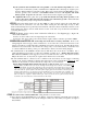
Copy this table and use it for recording the TriMetric TM-2030 History data. This data can be helpful to a technician trying to diagnose a problem with your system, or to verify that it appears to be operating normally. Also copy the data from program modes P1, P2 and P3 and copy it to the second chart at bottom: To access this data: 1. Set “Operating level” to L2 or L3 using program P7. See Section 5, Table 2, program item P7 on page 6 of these instructions for how to set to L2 or L3. 2.