
Spec Sheet


ARCHITECT & ENGINEER SPECIFICA
TIONS*
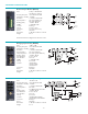
Microphone Input Module (MIC1S) The MIC1S module
shall have a transformer-isolated, balanced input with screw
terminal connector. It shall interface with low-impedance
dynamic microphones. It shall also interface with electret con-
denser microphones and shall have an internal 24V DC phan-
tom po
wer supply to provide the bias supply that is enabled
by a PCB jumper.The module shall have a gain control that will
allo
w the gain to be adjusted from 28 dB to 62 dB. It shall have
the ability to mute lower priority modules and be muted by
higher priority modules. The module shall be able to assume
any of 4 priority levels.The module shall have a VOX/gating cir-
cuit to control muting of lower priority modules and its inter-
nal gating circuit with controls for threshold and duration. It
shall have a built-in limiter, with a threshold control, to limit
the maximum output level of the module. The module shall
have bass and treble controls with cut or boost of
10 dB at
100 Hz and 10 kHz, respectively.The module’s output shall be
assignable to either or both of two mixing buses.
Microphone Input Module (MIC1X) The MIC1X module
shall have a transformer-isolated, balanced input with XLR
connector. It shall interface with low-impedance dynamic
microphones. It shall also interface with electret condenser
microphones and shall have an internal 24V DC phantom
power supply to provide the bias supply that is enabled by a
PCB jumper. The module shall have a gain control that will
allow the gain to be adjusted from 28 dB to 62 dB. It shall have
the ability to mute lower priority modules and be muted by
higher priority modules. The module shall be able to assume
any of 4 priority levels.The module shall have a VOX/gating cir-
cuit to control muting of lower priority modules and its inter-
nal gating circuit with controls for threshold and duration. It
shall have a built-in limiter, with a threshold control, to limit
the maximum output level of the module. The module shall
have bass and treble controls with cut or boost of
10 dB at
100 Hz and 10 kHz, respectively.The module’s output shall be
assignable to either or both of two mixing buses.
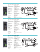
Micr
ophone Input Module (MIC2S)
The MIC2S module
shall have an electronically-balanced input with screw terminal
connector. It shall interface with low-impedance dynamic
microphones. It shall also interface with electret condenser
micr
ophones and shall ha
ve an internal 24V DC phantom
power supply to provide the bias supply that is enabled by a
PCB jumper. The module shall have a gain control that will
allow the gain to be adjusted from
18 dB to 62 dB. It shall have
the ability to mute lower priority modules and be muted by
higher priority modules. The module shall be able to assume
any of 4 priority levels.The module shall have a VOX/gating cir-
cuit to contr
ol m
uting of lo
w
er priority modules and its inter-
nal gating circuit with a threshold control . It shall have a built-
in limiter, with a threshold control, to limit the maximum out-
put le
vel of the module.The module shall have bass and treble
controls with cut only of
10 dB at 100 Hz and 3 kHz, respec-
tively.The module shall have a voice enhancement control for
impr
o
ving v
oice intelligibility. The module’s output shall be
assignable to either or both of two mixing buses.
Balanced Input Module (BAL2S) The BAL2S input mod-
ule shall be a ster
eo, high-impedance, electronically-balanced
input module. It shall be mutable by higher priority modules
and shall f
eature an internal PCB jumper to enable or disable
muting from the priority bus system. It shall have a continu-
ously variable ducking control that will enable attenuation of
the input signal from a minimum of
10 dB to a maximum of 48
dB r
elative to the normal unmuted condition.The module shall
have a rapid mute when the mute function is activated and a
gradual fade back from mute when the mute control is deac-
tivated. Gain shall be switch selectable per channel and shall be
0 dB or +
18 dB.
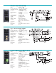
Bridging Input Module (BRG1R) The BRG1R input mod-
ule shall have a mono-balanced input and a buffered pseudo-
balanced output that will enable the connection of several
amplifiers to each other in a daisy chain configuration without
creating ground loops between units. It shall have an RCA jack
for both the input and the output connections. The module
shall have a gain/trim control that will allow the gain to be
adjusted plus or minus 5 dB relative to 0 dB nominal gain. It
shall have the ability to mute lower priority modules and be
muted by higher priority modules.The module shall be able to
assume any of 4 priority levels. It shall have a continuously
variable ducking control that will enable attenuation of the
input signal from a minimum of
10 dB to a maximum of 48 dB
relative to the normal unmuted condition and a gradual fade
back from mute when the mute control is deactivated. The
buffered output shall not be mutable.The module shall have a
VOX/gating circuit to control muting of lower priority mod-
ules and an internal gating circuit with controls for threshold
and duration.The module’s output shall be assignable to either
or both of two mixing buses.
Mono Aux Input Module (MAX1R) The MAX1R module
shall be a mono,
high-impedance, unbalanced input module.
The module shall have an RCA jack as its input connector.The
module shall have a gain/trim control that will allow the gain
to be adjusted from -20 dB to +6 dB relative to 0 dB nominal
gain. It shall have the ability to mute lower priority modules
and be muted by higher priority modules.The module shall be
able to assume any of 4 priority levels. It shall have a continu-
ousl
y variable ducking control that will enable attenuation of
the input signal from a minimum of 10 dB to a maximum of 48
dB relative to the normal unmuted condition and a gradual
fade back from mute when the mute or gate control is deac-
tivated.The module shall have a VOX/gating circuit to control
muting of lower priority modules and its internal gating circuit,
with controls for threshold and duration. The module shall
have bass and treble controls with cut or boost of
10 dB at
100 Hz and 10 kHz, respectively.The module’s output shall be
assignable to either or both of two mixing buses.
6
* Architect & Engineer Specifications are available on the Bogen website in a
Microsoft® Word document to assist you with preparing your bids.