CAM8-Series Models CAM8, CAM8PRO Installation and Use Manual © 2000 Bogen Communications, Inc. All rights reserved.
© 2000 Bogen Communications, Inc. All Rights Reserved. Notice Every effort was made to ensure that the information in this guide was complete and accurate at the time of printing. However, this information is subject to change. Important Safety Information Always follow these basic safety precautions when installing and using the unit: Read all instructions before installing or operating the unit. 2. Follow all warnings and instructions marked on the product. 3.
Contents INTRODUCTION............................................................................................................................................................................................4 Safety Instructions ................................................................................................................................................................................5 QUICK START ...........................................................................................
Introduction CAM8-Series This manual covers installation for both the CAM8 and CAM8PRO.They were manufactured to ensure the highest quality audio signal production and control, while still incorporating simple-to-use features. This manual is designed to familiarize you with the features of your new Bogen CAM8-Series mixer and to guide you through its installation and operation.
Safety Instructions Bogen’s CAM8-Series mixers are electrical equipment, so take all the precautions usually taken when installing and using electrical equipment (see inside front cover).To protect both the users and the equipment, pay particular attention to: • Grounding - Make sure both the mixer and the devices connected to it are properly grounded. • Power Supply - Use only the power supply provided or one that meets the manufacturer’s specifications.
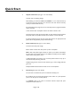
Quick Start 1. Unpack and Connect (See page 11 for more details). A. Check mixer for shipping damage. Rack Mounting: To mount the CAM8 and CAM8PRO to a 19” rack, lift the unit up to the front of the rack and secure it to the front of the rack with the necessary screws (not included with this unit). B. If special features (see page 18) are to be used, they must be programmed before mixer is mounted. C.Turn off both mixer and amplifier and turn all volume controls to zero. D.
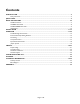
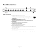
Panel Descriptions 2 4 5 CAM8 + + - + - M.A BUS 1 1 Low Cut + - M.A BUS 2 Low Cut + - M.A BUS 3 Low Cut + - M.A BUS 4 Low Cut + - M.A BUS 5 Low Cut + - M.A BUS 6 Low Cut - M.A BUS 7 Low Cut M.A BUS 8 Low Cut MAIN Power AUX 3 6 7 CAM8 Front Panel 1. Main/Auxiliary Bus Selector (one per channel) A 4-position switch which selects destination of channel input.
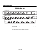
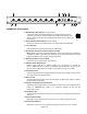
2 5 7 8 Threshold + + - + - M.A BUS 1 1 Low Cut + - M.A BUS 2 Low Cut + - M.A BUS 3 Low Cut + - M.A BUS 4 Low Cut + - M.A BUS 5 Low Cut 6 Low Cut - M.A BUS 7 Low Cut -40 On Off + - M.A BUS M.A BUS 8 Low Cut 3 Limit +20 -18 -12 -6 -3 MAIN 4 9 CAM8PRO Ratio 0 100 0 +3 +6 +12 AUX 6 Headphone 10 Power 11 12 CAM8PRO Front Panel 1. Main/Auxiliary Bus Selector (one per channel) + A 4-position switch which selects destination of channel input.
4 6 7 AUX OUT MAIN AUX IN 1 Ground 18VCT AC 8 Trim Trim 8 Trim 7 Trim 6 Trim 5 Trim 4 Trim 3 Trim 2 1 On Off Power Phantom 2 3 G - + -50dB 0dB G - + G - + Line Mic G - + Line Mic G - 5 + Line Mic 9 - G + Line Mic G - + Line Mic G - + Line Mic G - + Line Mic G - + Line Mic G - + 10 CAM8/CAM8PRO Rear Panel 1. Ground Connection on Rear Panel Access to ground. 2. AC Power Jack Mixer power supply input.
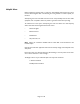
Helpful Hints Electrical equipment operates best in a clean, dry, well-ventilated environment free of vibration and electromagnetic fields. The following are some guidelines to achieve optimal performance. Avoid placing the mixer and cables near heat sources. Be particularly aware of other audio equipment, such as amplifiers, which can produce a great deal of heat when operating.
Installation Note: Take the mixer out of the box and inspect for shipping damage. If there is obvious physical damage to the outside of the mixer, contact the supplier of the mixer before you begin installation. Rack Mounting:To mount CAM8 and CAM8PRO to a 19” rack, lift the unit up to the front of the rack and secure it to the front of the rack with the necessary screws (not included with this unit). A.Turn all mixer Volume Control Knobs [Channel(s) (1), Main (2), and Auxiliary (3)] to zero.
C. Connect Output: Make a connection between Main Bus Output Terminals (3) and an input jack of an amplifier. Press Main Output Microphone/Line Switch (2) to appropriate position: “in” for line-level output (0 dBµ) or “out” for mic-level (-50 dBµ) output. 1 3 AUX OUT MAIN On Off Phantom G - + -50dB 0dB G - + 2 If desired, also connect Auxiliary Bus Output Terminals (1) to a second destination device. The auxiliary output is line-level only. D.
Operation The primary goal when establishing the gain settings of the mixers is to have each channel operating at the maximum gain without clipping, while leaving adequate headroom on the volume control knob. The channel Input Gain/Trim Control (1) on the rear panel of the mixers directly controls the microphone pre-amplifier gain available at each channel. 1 Trim 6 Line Mic G - + The Volume Control (2) on the front panel controls how much of the gain is routed to the main output stage.
Troubleshooting Gain Structure If the procedure followed to this point does not give satisfactory results, follow the appropriate adjustment sequence below: If channel clipping occurs If the signal is clipping or producing audible distortion, the gain is too high. Reduce the Input Gain/Trim Control (rear panel) by turning it counterclockwise until clipping does not occur.
Recommended Input Wiring Methods These are the best ways to connect sources to the mixer.The mixer input is always balanced. From the drawings below choose the wiring method for your input device (either balanced or unbalanced). Balanced Source to Balanced Input - Method 1 (Normal) Shown below is the normal wiring method for a balanced source device. It has +6 dB gain and excellent ground current and noise rejection.
Fine Tuning Low Cut Switch To remove excessive bass from an individual channel, press the Low Cut Switch (1) for that channel. + + - - M.A BUS 1 Low Cut M.A BUS 1 This feature helps eliminate low frequency noise (signals of 150 Hz and below, such as background rumble from ventilation systems, etc.) and is used primarily with mic-level input. It is particularly effective when handheld mics are used.
Compressor/Limiter (CAM8PRO only) 2 4 Threshold -40 Limit 1 Ratio +20 0 -18 -12 -6 -3 100 0 +3 +6 +12 MAIN 3 The Compressor/Limiter (1) is a dynamic range controller that can be used to compensate for signals that may sound unnatural or cause audible distortion.This is indicated by the LED Bar Graph Output Meter (3) occasionally exceeding +12 VU (red). Note: The Compressor/Limiter is only available on the CAM8PRO and only affects the main channel.
Special Features Activation The CAM8-Series mixers have several built-in features which are easily activated by making adjustments inside the mixer chassis. Changing the selection of all built-in features requires only the correct placement of internal jumpers or varying the settings of an internal potentiometer. Note:All the internal components — jumpers and potentiometers — to which adjustments are needed for built-in features are highlighted within dashed areas in the drawing below.
Jumper Options Changing Jumper Settings To change a jumper setting, remove the ten screws secured to the top of the mixer. After removing the top of the mixer, locate the jumper to be changed by referring to the drawing on page 18. Jumpers are included from the factory in positions: J2, J17, J18, J21, and J22. Warning: Disconnect AC Power before opening case. Bar Graph Options The mixer’s meter can be configured to meter the output of either the main or auxiliary bus.
Linking CAM8-Series mixers can be linked in several ways.The two principal ways of linking the mixers are Simple and Complex Linking. Simple Linking is the expansion to more than 8 inputs by connecting two 8-channel mixers via the auxiliary bus. Simple Linking is the “daisy-chaining” of multiple mixers to expand the number of inputs routed to a single output. Inputs can be multiplied in increments of 8 by adding mixers to the chain.
Simple Linking Simple linking or “daisy-chaining” allows the expansion of mixer inputs in multiples of 8 inputs by chaining together multiple mixers with auxiliary buses.To preserve certain mixer features, this must be done in the way shown below. Follow these steps (see page 18 for jumper locations): 1. For each mixer, remove the jumper from J2 and place it on J1.This causes the Auxiliary Out level to be set by an internal pot, fixing the linked gain structure.
Complex Linking Complex Linking allows multiple mixers to produce two separate mixes from the same set of inputs.The most common complex linking application is shown below.This method can also be used to implement a “mix minus” application. This method (CAM8PRO only) creates two separate mixes. Both destinations are routed through the Compressor/Limiter, since both destinations are driven by Main outputs.
AC Power Connection This mixer is powered by an 18 Volt, 1.5 Amp center-tapped transformer (supplied). If another AC supply is used, it should be of equal voltage and have at least a 21 Volt-Amp rating.The details of the AC Power Jack on the rear panel are as shown in the following figure. Center No connect AC AC Technical Support Our Applications Engineering Department is available to help you troubleshoot problems with your Bogen equipment.
Troubleshooting Tips NO POWER Check the connections between the mixer and the power supply and the external AC power supply. Examine the 4-pin connector as shown on page 23. Check the wall outlet. NO SOUND • • • • • Make sure the MIC/Line switch is in the proper position. (This is the most likely cause.) Make sure both the master and channel input controls are turned up. Check that the source signal cable(s) is properly connected and undamaged.
Glossary Auxiliary Input - Accepts only a balanced, line-level input (unlike the 8 channels); the auxiliary input has no volume control. Compression Ratio - The ratio of the output level above the threshold level to the input level above the threshold. Compression Threshold - The volume level, in dB, which is set as the optimum device operating level, and above which the Compressor/Limiter begins to operate.
Technical Information SPECIFICATIONS Signal-to-Noise MIC Pre-amp Equivalent Input Noise Maximum Voltage Gain Frequency Response Ref +26 dBV @ 54 dB sys gain = 90 dB -129 dB @ 150 ohm, 20 Hz to 20 kHz 96 dB ± 1 dB from 20 Hz to 20 kHz +0, -3 dB from 10 Hz to 30 kHz better than -90 dB +30V DC Crosstalk (adjacent channels) Phantom Power INPUTS 1-8 Input Impedance Nominal Source Impedance Line Pad Input Gain/Trim Range Nominal Level (input trim pot mid-range) Minimum Level (input trim pot max gain) Maximum Le
Auxiliary Circuits Bar Graph -18, -12, -6, -3, 0, +3, +6, +12 VU (0 VU = +4 dB) Average or Peak reading Peak reading per DIN spec. 45406 (1.7 ms attack, 650 ms decay) Compressor/Limiter Adjustment Range +20 dB to -40 dB Compressor/Limiter Ratio Adjustment Range 0 to 100% Low Cut Filter 12 dB/octave at 150 Hz Power Requirements 18V AC center-tapped, 21V AC/120V AC, 60 Hz ±18 - 24V DC, 450 mA Dimensions 19" W x 1-3/4" H x 6" D Shipping Weights (CAM8) (CAM8PRO) Page 27 of 32 10 lb. 10 lb.
PAD PAD Mic/line input -70/-50 dB -10/+10 dB Mic/line Mic/line input -70/-50 dB -10/+10 dB Mic/line +10 to +50 dB +10 to +50 dB In/out Hi Pass 150Hz In/out Hi Pass 150Hz Aux Line Input (Link Input) 20 dB 20 dB INPUT 2 INPUT 1 Page 28 of 32 J18 J17 Aux Bus Main M A M A 20 dB J23 Main Aux J22 Meter Main volume 20 dB Limit in/out Post Pre AREAS IN DASHED LINES DO NOT APPLY TO THE CAM8 Sum Limiter Control Ratio J2 J1 Pre-gain RP 23 Threshold Aux volume Sum 20 dB 6 dB
Warranty The CAM8 and CAM8PRO are warranted to be free from defects in material or workmanship for two (2) years from the date of sale to the original purchaser.Any part of the product covered by this warranty that, with normal installation and use, becomes defective will be repaired or replaced by Bogen, at our option, provided the product is shipped insured and prepaid to: Bogen Factory Service Department, 50 Spring Street, Ramsey, NJ 07446, USA.The product will be returned to you freight prepaid.
Page 30 of 32
Page 31 of 32
50 Spring Street, Ramsey, NJ 07446 Tel. 201-934-8500, Fax: 201-934-9832 www.bogen.