
Installation Manual


5
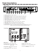
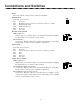
Panel Descriptions
1. Power - Input jack for power connection.
2. Override Input - RJ11 jack for both loop start and dry audio input sources.
3. Override Control Switch - Selects either dry loop (DL) or loop start (LS).
4. Page In Input - RJ11 jack for both dry audio and loop start applications.
5. Page In Control Switch - Selects either dry loop (DL) or loop start (LS).
6. Audio Out Volume Control - Output volume control.
7. Audio Out Impedance Selector - Selects either 8-ohm or 600-ohm.
8. Audio Out - RJ11 jack for Audio Out w/Status Signal Connector.
9. Setup Switches - DIP switch settings control unit feature operation.
10. I/O Connections - Various control inputs and status outputs are available at this connector.
All I/O connections are electrically isolated from the unitʼs chassis.
Bottom Panel
Front Panel
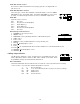
LED Indicators
11. Power - Green, power is applied to unit
12. Override Active - Yellow, indicates override
input is active
13. Page Active - Yellow, indicates page input
is active
14. Audio Trigger - Green, audio is detected
15. Busy - Yellow, unit is active
16. Play - Green, unit is actively playing a page
17. Record - Red, unit is actively recording
a message
11
12
13
14
15
16
17