54-2091-01E_54-2091-01B.qxd 3/6/13 4:21 PM Page 1 High-Fidelity Ceiling Speakers Models HFCS1 & HFCS1LP (Off-white), HFCS1B & HFCS1LPB (Black) Installation and Use Manual © 2006 Bogen Communications, Inc. All rights reserved. Specifications subject to change without notice.
54-2091-01E_54-2091-01B.qxd 3/6/13 4:21 PM Page 2 Product Description Bogen’s coaxial 2-way hi-fi ceiling speakers deliver unsurpassed performance and value. The steel back can and front exit venting allow for deep bass response, enhancing the quality and intelligibility of both speech and music. The HFCS1LP uses a smaller, low-profile back can that allows for a greater range of installations. The speakers are available with off-white finish or black finish (B versions).
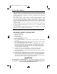
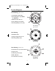
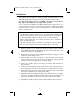
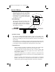
54-2091-01E_54-2091-01B.qxd 3/6/13 4:21 PM Page 3 Product Diagrams Front Drawing (grille removed) 1. Coaxial Driver Assembly 2. Bass Tuning Vents (x2, HFCS1; x1, HFCS1LP) 3. Grille Retention Groove 4. Power Tap Selection Switch 5. Mounting Clamp Screws (x4) Front Drawing (grille removed) Rear Drawing 6. Metal Back Can 7. Snap-Lock Input Connector 8. Mounting Clamps (x4) Rear Drawing Rear Drawing (terminal cover) 9. Terminal Covers (2 identical halves) 10. Eyelets (x2) 11. Mounting Screws (x4) 12.
54-2091-01E_54-2091-01B.qxd 3/6/13 4:21 PM Page 4 Installation The speakers can be installed in a variety of ceiling environments. The use of the TBCR (Tile Bridge Support Ring) accessory may be desired for many of these. For suspended ceilings, the use of a TBCR is strongly recommended to help support and distribute the weight of the speaker. In new construction installations the TBCR, installed before sheetrock, acts as a routing template that ensures an accurate and neat hole for installation.
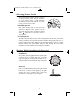
4-2091-01E_54-2091-01B.qxd 3/6/13 4:21 PM Page 5 Speaker Wiring All wiring should be done prior to installation and then plugged into the rear of the speaker. Wiring is terminated at a snap-lock input connector. There are two positive and two negative terminals to accommodate daisy-chaining of speakers in a system. Daisy-Chaining The snap-lock input connector allows for easy daisy-chaining of speakers by providing a second terminal of each polarity.
54-2091-01E_54-2091-01B.qxd 3/6/13 4:21 PM Page 6 Selecting Power Levels The front-mounted selector switch is used to set the appropriate power level or impedance for your system. Using a small, flat-blade screwdriver, turn the knob until the slot points to the power level you require. 70V/100V Systems Both power setting scales for 70V and 100V systems are labeled on the speakers. On the 100V scale, the last position clockwise is marked with a symbol. Do not use this position in 100V systems.
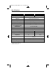
54-2091-01E_54-2091-01B.qxd 3/6/13 4:21 PM Page 7 Specifications SPECIFICATIONS HFCS1 HFCS1LP Frequency Response (-10 dB)* 65 Hz to 19 kHz 78 Hz to 19 kHz LF Driver 6-1/2" (165mm) Polypropylene Cone HF Driver 3/4" (20mm) Polycarbonate Cone Sensitivity (1W/1m) 89 dBspl (Average 100 Hz - 10 kHz) Impedance Ratings Low (16 ohms) / High (70V/100V) Power Input (Max.
54-2091-01E_54-2091-01B.qxd 3/6/13 4:21 PM Page 8 Accessories TBCR (Tile Bridge Support Ring) The TBCR is a combination tile bridge and support ring that assists in securing the HFCS1(B) /HFCS1LP(B), and in distributing the weight of the speaker in various types of installations. CK10 (Cable Kit, 10') The CK10 is a 10-foot cable with one looped end and an adjustable cable clamp. It is suitable for use as a safety cable (see Terminal Covers on page 3).