
Manual


LMM1S
LMM1S
MIC/LINE
MIC/LINE
IN
IN
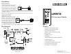
LMM1S
Mic/Line Input Module
Features
• Line mode for high impedance input
• MIC Mode for low impedance input
• Electronically balanced input
• Gain/Trim control with Gain range switch
• Bass and treble
• 24V Phantom power
• Audio Gating
• Gating with threshold and duration adjustments
• Fade back from mute
• 4 levels of available priority
• Can be muted from higher priority modules
• Can mute lower priority modules
• Removeable screw terminal input
© 2007 Bogen Communications, Inc.
54-2156-01A 0706
Specifications subject to change without notice.
50 Spring Street, Ramsey, NJ 07446, U.S.A.
201-934-8500; Fax: 201-934-9832
www.bogen.com
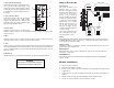
Block Diagram
INPUT
ATTEN.
+
_
GND
MIC/LINE
INPUT
MIC/LINE
Input Wiring
Balanced Connection
Use this wiring when the source equipment
supplies a balanced, 3-wire output signal.
Connect the shield wire of the source signal
to the "G" terminal of the input. If the "+"
signal lead of the source can be identified,
connect it to the plus "+" terminal of the input. If the source lead polarity cannot be identified,
connect either of the hot leads to the plus "+" terminal. Connect the remaining lead to the minus
"-" terminal of the input.
Note: If polarity of the output signal versus the input signal is important, it may be necessary to
reverse input lead connections.
Unbalanced Connection
When the source device provides only an
unbalanced output (signal and ground),
the input module should be wired with
the "-" input shorted to ground (G). The
unbalanced signal's shield wire is con-
nected to the input module’s ground and
the signal hot wire is connected to the
"+" terminal. Since unbalanced connections do not provide the same amount of noise immunity
that a balanced connection does, the connection distances should be made as short as possible.
SOURCE
EQUIPMENT
MIC/LINE
MIC/LINE
IN
IN
MIC/LINE
MIC/LINE
IN
IN
SOURCE
EQUIPMENT
JUMPER WIRE