Ambient Noise Sensor Model ANS501 Installation and Use Manual © 2003 Bogen Communications, Inc. All rights reserved. Specifications subject to change without notice. 54-2096-01A Printed in Korea.
Notice IMPORTANT Every effort was made to ensure that the information in this guide was complete and accurate at the time of printing. However, information is subject to change. Important Safety Information CAUTION: TO PREVENT THE RISK OF ELECTRIC SHOCK, DO NOT REMOVE COVER (OR BACK). NO USER-SERVICEABLE PARTS INSIDE. REFER SERVICING TO QUALIFIED PERSONNEL. WARNING: To Reduce The Risk of Fire Or Electric Shock, Do Not Expose This Apparatus To Rain Or Moisture.
Contents Page DESCRIPTION ....................................................................................................................4 Package Contents ................................................................................................................................4 Features..................................................................................................................................................4 PANEL DESCRIPTIONS ..............................................
Description The Bogen Model ANS501 Ambient Noise Sensor is designed to electronically adjust the level of a page announcement or background music in an area of a building where ambient noise levels are continuously changing. It ensures that page announcements or background music are intelligible even during periods of high ambient noise levels. The ANS501 monitors the ambient noise level through the use of an ANS500M sensor microphone module.
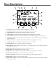
Panel Descriptions 1. Aux Input - Mono summing, stereo, unbalanced RCA inputs on side panel. 2. AUX Level Control - Controls the AUX input level feed directly to the output. 3. Unbalanced Input - High-impedance unbalanced RCA input on side panel. 4. Balanced Input - High-impedance electronically balanced input (pluggable screw terminal). 5. Sensor MIC Input - Input connections for ANS500M sensor microphone(s) (pluggable screw terminal). 6.
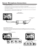
Sensor Microphone Connections Sensor Microphone Wiring • The ANS501 requires connection of at least one sensor microphone for operation.To allow for better ambient noise sensing of large areas, up to 4 sensor microphones can be connected to a single ANS501. • All microphones are wired in parallel matching the polarity markings on the sensor mic with the marking of the two MIC terminals on the ANS501.
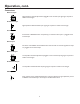
Operation Front Panel Controls AUX Level Control Controls the AUX input level, which is bussed directly to the output. Aux signal bypasses gain riding. Relative Gain Control Sets the relative amount of gain maintained above the ambient level. Range is 1 dB to 24 dB of gain. Ramp Speed Control Sets the speed by which gain is increased/decreased to the signal once the ambient noise level is above/below the threshold, from less than 1 dB/s (slow) to greater than 20 dB/s (fast).
Operation, cont. Connections Balanced Input High-impedance, electronically balanced, pluggable screw terminal input. Signal gain responds to ambient noise changes. Unbalanced Input High-impedance unbalanced RCA input. Signal gain responds to ambient noise changes. Sensor MIC Connections to ANS500M sensor microphone(s) are made here.The input is a pluggable screw terminal input. Defeat Input The effects of the ANS1R will be defeated when these terminals are shorted together.
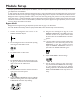
Module Setup All inputs (balanced and unbalanced) into the ANS501, with the exception of the Aux input, will be affected by the automatic gain adjustments of the ANS501. In audio systems that provide continuous background music, it may be desirable to have the background music stay at a fixed level but have all other source inputs (like a paging microphone) change level in response to the ambient noise level in an area.
Module Setup, cont. Normal Mode All sources are affected by the gain adjustment process. Background music source will need to be routed through the main mixer inputs, which will be affected by the gain adjustment process. Refer to page 12 for illustration. Start with all POTS turned fully clockwise (AUX IN is not used in this mode). 1. Set MODE Switch to "SET" mode. 2. Set RELATIVE GAIN to the desired amount of signal gain you would like the balanced/unbalanced input to ride over the ambient level. 3.
Bypass Mode Illustration Module Setup, cont.
Normal Mode Illustration Module Setup, cont.
Ambient Level Settings Use this table to estimate the general dBspl level of the area’s ambient noise if actual measurements are not available.
Block Diagram 14
Limited Warranty The ANS501 is warranted to be free from defects in material or workmanship for two (2) years from the date of sale to the original purchaser.Any part of the product covered by this warranty that, with normal installation and use, becomes defective will be repaired or replaced by Bogen, at our option, provided the product is shipped insured and prepaid to: Bogen Factory Service Department, 50 Spring Street, Ramsey, NJ 07446, USA.The product will be returned to you freight prepaid.
50 Spring Street, Ramsey, NJ 07446, U.S.A. Tel. 201-934-8500, Fax: 201-934-9832, www.bogen.