PCM Paging Control System Installation and Use Manual Issue 2, October 1999 © 1999 Bogen Communications, Inc. All rights reserved.
© 1999 Bogen Communications, Inc. All Rights Reserved. Printed in U.S.A. Notice Every effort was made to ensure that the information in this guide was complete and accurate at the time of printing. However, information is subject to change. FCC Statement (Part 15) - Radio Frequency Interference The PCM2000 System generates and uses radio frequency energy and if not installed and used in strict accordance with the manufacturer's instructions, may cause interference to radio and television reception.
Contents 1. Introduction..........................................................................................................................5 1.1. Voice Channel ..........................................................................................5 1.2. Background Music ....................................................................................6 1.3. Signaling Channel ....................................................................................6 1.4. Other Features ...............
8. Zone Speaker Wiring and Setup ......................................................................................................31 8.1. Wiring to 70V speakers ..........................................................................................31 8.2. Wiring to Self-Amplified Speaker or Dedicated Amplifier....................................31 8.3. Setting a Zone for Talk Back Operation ................................................................31 9. Optional Wiring......................
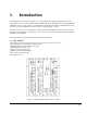
1. Introduction The PCM Paging Control System (see Figure 1-1) is an expandable zone paging and signaling system. The LUPCMALL consists of 4 pre-assembled modules: PCMTIM, PCMCPU, PCMTBM, and a Zone Paging Module (PCMZPM). To this, you can add up to two additional Zone Paging Modules (Model: LUPCMZONE, Pec Code 5323-108, Com Code 408186039) to increase system zone paging capacity to 9 zones.
1.2. Background Music • High/Low-Power distributed (buffered for up to 50 amplified speakers) • High/Low-Powered, using dedicated BGM amplifier • High/Low-Powered using a single paging/BGM amplifier • BGM Disable to individual zones • Local BGM input on each individual zone module 1.3.
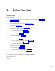
2. Before You Start 2.1. Select Options Before setting up your system, use the checklist below to assist you in setting up and programming the PCM Paging Control System. ____ Type of Telephone Interface (loop start, ground start, page port, station port) (see System Wiring Connections, Section 5) ____ Total Number of Paging Zones (additional Zone Paging Modules or LUPCMADD Paging Control System Assemblies may be required) (see Installation, Section 3) ____ Zone Groups (see Section 11.
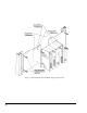
Figure 3-1: Rack Mounting the LUPCMALL Paging Control System [8]
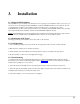
3. Installation 3.1. Adding PCMZPM Modules The LUPCMALL is pre-assembled to accommodate 3 zones of paging. If your installation requires 4 to 9 zones, you can add one or two Zone Paging Modules (PCMZPM). A total of 3 PCMZPM modules (9 zones total) can be used on a LUPCMALL assembly. If your installation requires more than 9 zones, you will need one or more LUPCMADD units to allow system expansion beyond 9 zones. Install the extra PCMZPM modules before mounting and wiring the PCM System assemblies.
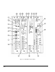
Figure 4-1: LUPCMALL Feature Callouts [10]
4. LUPCMALL Feature Callouts Descriptions and Locations Refer to Figure 4-1. 1. TEL INT SEL Switch Bank - Sets telephone interface type for the TEL LINE jack on the PCMTIM module (see Section 5). 2. POWER - Indicates that power has been supplied to the module. One exists on each module. 3. TONE VOLUME - Controls the level of all tones produced by the PCM system. 4. BGM SRC VOLUME - Sets background music level for one mode of operation.
15. TALK BACK Switch Bank - Determines if a 70V speaker zone will operate as a two-way hands-free talk back zone or as a one-way paging zone (see Section 8.3). 16. TALK BACK DELAY - Controls the amount of delay, after speaking stops, before the system switches to the listen mode during talk back operation (see Section 8.3). 17. TALK BACK VOLUME - Controls the audio level of the talk back signal (see Section 8.3). 18. NOISE REDUCTION - Enables or disables noise reduction during talk back listening.
❑ 5. System Wiring Connections 5.1. Telephone System Connections The PCMTIM module is the telephone interface module for the PCM Paging Control System. The PCMTIM provides the telephone interface (including talk battery), night ringer input, emergency over ride input, and auxiliary relay contacts for the system. The module is also responsible for all tone signaling features.
IMPORTANT: The polarity of the Tip & Ring contacts of the RJ11 jack for the Tel Line and Over Ride were chosen so that when a standard modular cord (one with the tops of both end plugs on the same side of the flat cable) is used to connect the PCM to a modular wall block, the modular block G (Tip) terminal will be positive with respect to the R (Ring) terminal.
4. Use 24-gauge solid wire to connect the GND ST terminal on the module to the PBX ground. This is typically the AC ground for the PBX system. IMPORTANT: It is very important that no other terminals of the PCM system connect to AC ground when using the ground start interface. Also, the case of the PCM system cannot be connected to AC ground. If the system is not working and no PCM terminals (except the GND ST terminal) are directly connected to AC ground, there may be an indirect connection.
The unit will also respond to CPC pulses (short losses of loop current). When a CPC pulse is detected, the unit will immediately drop the line. 1. Make sure that power is off and all connections completed before proceeding. 2. Move the TEL INT SEL (dip) switches on the module to the position shown in Figure 5-7 below. Use the tip of a pen or other pointed instrument to move the switches. Figure 5-7: Station Telephone Selector Switch 3.
The night ringer normally sounds a simulated ring tone but can be programmed to sound a chime tone. Refer to System Programming, Section 11 to set up a night ringer zone group or to change to ringer tone. To physically connect the night ringer wiring: 1. Make sure that power is off. 2. Plug a modular cord into the NIGHT RING (RJ11) jack. The center conductors of the plug are used for the 90V ring signal (see Figure 5-9). The flanking conductors are used for contact closure activation.
[18]
6. Paging Amplifier Connections The paging amplifier audio connections are made to the PCMTBM module terminal strip. If the amplifier has a paging control input, this is connected to the RLY TWO terminals on the PCMTIM module (see Figure 6-1). The paging amplifier must have a balanced 600-ohm input. The amplifier should be located close to the PCM system to keep cable lengths reasonably short. NOTE: To make all audio connections, use 22 AWG shielded, twisted pair on all wire runs.
[20]
7. Background Music The PCM system is very flexible in how it can provide background music throughout the system: • Background music can be continuously supplied to all zones not being paged. (Requires two amplifiers of the same power rating.) • Background music can be supplied by the same amplifier that is supplying paging. (Music input is available on amplifier.) • Background music can be supplied by same amplifier that is supplying paging. (No dedicated music input available on amplifier.
[22]
7.2. Background Music Continuously Supplied To All Zones Not Being Paged See Figure 7-1 on page 20 for connection with a high-powered background music source or Figure 7-2 on page 22 for connection with a low-powered background music source. NOTE: Requires second amplifier of the same power rating as the paging amplifier. NOTE: This configuration is not recommended for systems that will use zones with talk back. 7.3.
[24]
[25]
[26]
[27]
This page intentionally left blank [28]
8. Zone Speaker Wiring and Setup 8.1. Wiring to 70V Speakers See Figure 8-2 on page 30 for wiring. NOTE: Make sure PCMZPM OUTPUT switch is set to HI PWR. To set the switch, remove the locking plate, place switch in desired position, and re-secure the locking plate. The locking plate can be rotated to match the switch setting. 8.2. Wiring to Self-Amplified Speaker or Dedicated Amplifier See Figure 8-3 on page 31 for wiring. NOTE: Make sure PCMZPM OUTPUT switch is set to LO PWR.
Figure 8-2: Zone Wiring to Speakers [30]
[31]
Figure 9-1: Connection of Relays to the Relay Driver Outputs [32]
9. Optional Wiring 9.1. CPU to Emergency Signaling External input control is available to trigger a tone signal from the PCM over the paging system. Shorting EM/SC to the GND terminal will produce a user-programmed tone into a specific zone group. This feature is typically used to signal shift changes using a contact closure pair from an external master clock. The tone signal can be directed to a specific group of zones by programming them into the EM/SC zone group.
This page intentionally left blank [34]
10. Power-Up of PCM and Associated Equipment 10.1. Power-Up Sequence All equipment in the paging system should remain off until the system wiring is completed. This is the recommended power-up sequence of the paging equipment after initial wiring: 1. Double check that all PCMZPM modules are set for the correct type of operation - HI PWR for 70V speakers or LO PWR for self-amplified speakers and dedicated amplifiers. 2. Turn all system volume controls to minimum. 3.
This page intentionally left blank [36]
11. System Programming System programming lets you set certain PCM options and tone features using the DTMF keys of a telephone. It also lets you to program paging zone groups and signaling zone groups. All programming is accomplished through the TEL LINE jack on the PCMTIM module regardless of the telephone interface used.
11.1. Programming Paging Zone Groups 32 paging zone groups can be created. Each zone group can consist of up to 99 zones. To create a zone group: 1. Dial [*] followed by 2-digit number of zone group (01 - 32) you want to create. Follow this with the 2-digit number of the zones you want to include in the zone group.
11.6. Single Amp BGM Enable Single amplifier BGM operation lets the PCM use the paging amplifier to provide high-powered BGM to passive speakers when the paging system is idle. When this option is enabled, the BGM SRC terminals are connected to the paging amplifier's input and HPBGM bus is connected to the paging amplifier's output. As soon as the PCM System becomes active, the BGM SRC and HPBGM connections to the paging amplifier are removed and the amplifier is ready for paging.
11.11. Relay Contacts The PCM system provides a set of dual "C-form" contacts which can be used to activate external equipment. The relay contacts are rated at 2A @ 30V DC/0.6A @ 120V AC (resistive). The relay changes state whenever a zone is active, and stays in this state until the zone page is completed.
12.
FEATURE FEATURE CODE ADDITIONAL DATA DEFAULT Zone Group No Tone Follow Contact 2-Second Tone 3-Second Tone 4-Second Tone 5-Second Tone 6-Second Tone 7-Second Tone Chime Quad Beep *92 020 021 022 023 024 025 026 027 028 029 Zone Numbers All Call Night Ring Zone Group No Tone Simulated Ring Chime *93 030 031 032 Zone Numbers Code Call Zone Group Inhibit Pattern Echo 1 Play 1 Repeat 2 Repeat *94 040 041 042 043 044 045 Zone Numbers Clock Set 060 HHMM 00:00 Clock Synchronization Inhibit Enable
FEATURE FEATURE CODE ADDITIONAL DATA DEFAULT Time Trigger 2 Zone Group Inhibit Enable 2-Second Tone 3-Second Tone 4-Second Tone 5-Second Tone 6-Second Tone 7-Second Tone 8-Second Tone Chime *82 120 121 122 123 124 125 126 127 128 129 Zone Numbers No Zones Inhibit See Note (page 44) Time Trigger 3 Zone Group Inhibit Enable 2-Second Tone 3-Second Tone 4-Second Tone 5-Second Tone 6-Second Tone 7-Second Tone 8-Second Tone Chime *83 130 131 132 133 134 135 136 137 138 139 Zone Numbers Time Trigger 4 Z
FEATURE FEATURE CODE ADDITIONAL DATA DEFAULT Time Trigger 6 Zone Group Inhibit Enable 2-Second Tone 3-Second Tone 4-Second Tone 5-Second Tone 6-Second Tone 7-Second Tone 8-Second Tone Chime *86 160 161 162 163 164 165 166 167 168 169 Zone Numbers No Zones Inhibit See Note 3 (below) Time Trigger 7 Zone Group Inhibit Enable 2-Second Tone 3-Second Tone 4-Second Tone 5-Second Tone 6-Second Tone 7-Second Tone 8-Second Tone Chime *87 170 171 172 173 174 175 176 177 178 179 Zone Numbers Time Trigger 8 Z
13. Paging: How To Use The PCM 13.1. Paging Zones The PCM system supports from 3 to 99 different paging zones (in groups of 3). It also supports up to 32 paging zone groups for voice paging application, and 11 zone groups for signalling applications (night ring, code call, EM/SC, 8 time triggers). Each zone group consists of 1 to 99 (user-programmed) zones. Paging zone groups are accessible by dialing a specific zone group number through the telephone.
13.5. How To Make A Code Call Code calling is the ability to activate a series of chime tones over a signalling zone group (the specific zones in the zone group are determined by the user - up to 99 zones). The PCM supports pattern and echo code calling. • Pattern Code Calling sounds a factory-set pattern of chime tones in response to a single keypad selection. • Echo Code Calling sounds chime tones that correspond to the actual 2-digit keypad numbers entered.
13.7. How To Make An Echo Code Call Refer to System Programming, Section 11, for instructions on how to activate this feature and to select the type of code call, and/or activate the auto repeat feature. 1. Dial the paging access number for your telephone system. 2. Listen for the confirmation tone if enabled (a double beep). 3. Press [#] and two number keys, then hang up. Example: [#] [3] [1] produces three tone bursts followed by a single tone burst. You must always enter two digits.
This page intentionally left blank [48]
14. Testing and Troubleshooting Functional Test Guide Use the following chart to verify proper operation after installation. To start the test, pick up a telephone and dial the access code for the port to which the PCM is connected. Does the PCM activate? The PCM is activated if it returns a confirmation tone over the telephone. NO Check List 1. Double check for correct wiring to PCMTIM. 2. Ensure connections are making proper contact. 3. Check power supply. (Be sure all LEDs are lit on each module.) 4.
Procedure A Refer to Figure 14-1 on page 51. 1. Disconnect PCM from the telephone system. 2. Set dip Switch 3, 4, and 5 to ON and 1, 2, 6, and 7 to OFF on the PCMTIM. 3. Connect a telephone test set/2500-type telephone to the TEL line input of the PCMTIM. 4. Go off hook with the test set/2500-type telephone. 5a. If confirmation tone is heard and a page can be made, the PCM telephone interface is working correctly. Go to Procedure B.
Figure 14-1: Test Procedure A.
[52]
Appendix A: Applications Typical Connections * To Slave Amps (see Figure A-2 on page 54) * To Ambient Level Controller (see Figure A-3 on page 55) * To Call Stacker (see Figure A-4 on page 56) * To Digital Feedback Eliminator (see Figure A-5 on page 56) * To Multiple Digital Message Unit (see Figure A-6 on page 57) * To Operate Door Speakers (see Figure A-7 on page 58) * Connecting to an External Audio Source (see below) Connecting to an External Audio Source A contact closure and dry audio source can also
[54]
Figure A-3: Typical Application - Connecting to an Ambient Level Controller [55]
Figure A-4: Typical Application - Connection to a Call Stacker Figure A-5: Typical Application - Connection to a Digital Feedback Eliminator [56]
[57]
[58]
Appendix B: Tones Confirmation Tone - A double-beep tone heard by the caller after dialing the paging access number and before entering the desired zone number. The default for the tone is enabled. The tone can also be inhibited. See System Programming, Section 11, if you wish to inhibit this tone. Emergency/Shift Change (EM/SC) Tone - This tone is activated when the EM/SC terminal on the PCMCPU module is shorted to the GND terminal. (Refer to the instructions included with the PCMCPU module for wiring.
This page intentionally left blank [60]
Appendix C: Glossary of Programmable Features 1-Amp BGM: Enabling this feature allows a single amp to provide background music (BGM) and paging throughout the system (BGM is lost in all zones during a zone page). This feature must be disabled when using a separate BGM amplifier and a paging amplifier. All-Call: System-wide all-call announcements made by dialing 00 can be inhibited. Clock Set: The real time clock in the PCM is set using a 24-hour time format with this feature.
Time Triggers (1-8): Eight separate time-triggered tones can be programmed into the PCM. A specific zone group can be programmed for each time-triggered tone, the time of the trigger, as well as the length or type of tone. Time tones can be inhibited and re-enabled without losing previously set trigger times. VOX Timer: The length of a silence interval before the PCM disconnects the page in station mode is set by this feature. It can be set in 1 second increments from 1-9 seconds.
Appendix D: Configuration Forms * Zone Configuration (Form D-1 on page 64) * Zone Group Map (Form D-2 on page 68) [63]
Form D-1: Zone Configuration Description Physical Physical Music Talk Back Night Ring Zone Zone in Zone in Zone in Zone Number Code Y/N Y/N Y/N 1 1 2 2 3 3 4 4 5 5 6 6 7 7 8 8 9 9 10 10 11 11 12 12 13 13 14 14 15 15 16 16 17 17 18 18 19 19 20 20 21 21 22 22 23 23 24 24 25 25 26 26 27 27 Expansion 1 Expansion 2 64 Configuration Forms
Form D-1: Zone Configuration (Continued) Description Physical Physical Music Talk Back Night Ring Zone Zone in Zone in Zone in Zone Number Code Y/N Y/N Y/N 28 28 29 29 30 30 31 31 32 32 33 33 34 34 35 35 36 36 37 37 38 38 39 39 40 40 41 41 42 42 43 43 44 44 45 45 46 46 47 47 48 48 49 49 50 50 51 51 52 52 53 53 54 54 Expansion 3 Expansion 4 Expansion 5 Configuration Forms 65
Form D-1: Zone Configuration (Continued) Description Physical Physical Music Talk Back Night Ring Zone Zone in Zone in Zone in Zone Number Code Y/N Y/N Y/N 55 55 56 56 57 57 58 58 59 59 60 60 61 61 62 62 63 63 64 64 65 65 66 66 67 67 68 68 69 69 70 70 71 71 72 72 73 73 74 74 75 75 76 76 77 77 78 78 79 79 80 80 81 81 Expansion 6 Expansion 7 Expansion 8 66 Configuration Forms
Form D-1: Zone Configuration (Continued) Description Physical Physical Music Talk Back Night Ring Zone Zone in Zone in Zone in Zone Number Code Y/N Y/N Y/N 82 82 83 83 84 84 85 85 86 86 87 87 88 88 89 89 90 90 91 91 92 92 93 93 94 94 95 95 96 96 97 97 98 98 99 99 Expansion 9 Expansion 10 All Zones are accessed by 00 Configuration Forms 67
From D-2.