Bogen Model PCMCPU Central Processing Module for Bogen's PCM2000 Zone Paging System © 2001 Bogen Communications, Inc. All rights reserved.
PCMCPU FCC Required Statements WARNING: Changes or modifications to this unit not expressly approved by the party responsible for compliance could void the user's authority to operate the equipment. FCC Requirements This equipment is component registered with the Federal Communications Commission (FCC) in accordance with Part 68 of its rules. In compliance with the rules, be advised of the following: 1.
PCMCPU Contents Section 1: Overview Description ......................................................................................................4 PCM2000 System ..........................................................................................4 Voice Channel ................................................................................................4 Background Music (BGM) ..............................................................................5 Signaling ............................
PCMCPU Section 1 Overview Description The Bogen Model PCMCPU is the microprocessor module for the Bogen PCM Zone Paging System. One module is required per assembly (up to three PCMZPM zone modules). The PCMCPU module provides power, data and audio connections for the PCM system. The PCMCPU module is connected to other PCM modules electrically through internal cables. Modules are mechanically joined by sliding together interlocking tabs and securing with a screw on the rear panel.
PCMCPU Background Music (BGM) • Low-power distributed (buffered for up to 50 amplified speakers) • High-power, using dedicated BGM amplifier • High-power using a single paging/BGM amplifier • BGM disable to individual zones • Local BGM input on each individual zone module Signaling • Night ringer (90V or contact closure activation) • Code calling (2 types - echo & pattern) • Emergency/shift change tone (tone and duration selectable) Other Features • DTMF setting of all operating parameters • External C-fo
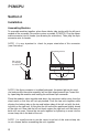
PCMCPU Section 2 Installation Assembling Modules To assemble modules together, place them side by side starting with the left most module of the assembly (for master system assembly, PCMCPU). Plug the ribbon cable connector into its header (see drawing for orientation). Then plug the 6-pin connector onto its header. NOTE: It is very important to check for proper orientation of this connector (see illustration). Align polarizing tab in slot Align connectors so locking ridge faces header wall.
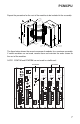
PCMCPU Repeat the procedure for the rest of the modules to be included in the assembly. LOCKING TAB LOCKING SLOT ALIGN CONNECTORS SO LOCKING RIDGE FACES HEADER WALL ALIGN . POLARIZING TAB IN SLOT LOCKING TAB LOCKING SLOT SCREW CLAMP TAB & SLOT The figure below shows the correct sequence of modules for a maximum assembly. If certain modules are not used, remove them and maintain the order shown for the rest of the modules. NOTE: PCMTIM and PCMTBM are not used in satellite unit.
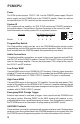
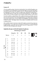
PCMCPU Power The PCM system requires 12V DC 1.5A. Use the PCMPS2 power supply. Plug the power supply into the POWER jack on the PCMCPU module. Power can also be connected to the 12V DC terminals on the connector block. System ID For a system with no satellites, set SYS ID DIP switches on PCMCPU module to the position shown. See section on System Expansion in this manual for additional information on setting system IDs in expanded systems.
PCMCPU Section 3 System Expansion Concept In situations where it is necessary to extend beyond 9 zones of paging, satellite systems and a master must be used. Each satellite system is responsible for the specific group of zones as determined by the setting of its SYS ID DIP switches. The master system transmits its commands on the Data Link bus to all satellites at the same time, but only the specifically addressed satellite responds.
PCMCPU System ID Once the satellite systems have been wired together, the satellite ID numbers can be assigned. The ID for the master system (the one which has the PCMTIM module) must be set to zero (all SYS ID switches set to "0"). Although satellite systems can be numbered in any order, it is best to number them sequentially, starting with "1" and following the way in which they are daisy-chained together.
PCMCPU Section 4 Paging System Assemblies: Applications and Illustrations Introduction The examples and illustrations shown on the following pages are typical paging system configurations. For improved clarity, these illustrations show the modules separated from each other. In actual systems, all modules in an assembly are physically connected.
PCMCPU One-Way Paging System with Satellites The illustration on the next page shows the wiring between different assemblies in a system with satellites for one-way paging. Four pairs of audio wires are daisychained between adjacent assemblies. These pairs are for the high-power paging and background music (PA OUT and RT and HPBGM IN and RT), and the lowpower paging and background music (PA IN and RT & LPBGM IN and RT).
MASTER ASSEMBLY 70V COM R BOGEN PAGING AMPLIFIER T AMPLIFIER 1 for Master Assembly SATELLITE ASSEMBLY #1 PCMCPU One-Way Paging System with Satellites 13
PCMCPU Two-Way Talkback Paging System with Satellites Information relative to connecting the system to the telephone system can be found in the instructions supplied with the PCMTIM module. The illustration on the next page shows the wiring for a PCM2000 system with satellites using talkback. This configuration is essentially the same as the one-way system described previously, 4 pairs of wires connect between all adjacent PCM2000 assemblies.
T R COM BOGEN PAGING AMPLIFIER 70V MASTER ASSEMBLY SATELLITE ASSEMBLY #1 PCMCPU Two-Way Talkback 15
PCMCPU 3-Zone System with One-Way Paging & Single Amp BGM The application illustrated on the next page shows the simplest PCM2000 system configuration. A single amplifier supplies both paging and BGM to passive speakers. As a result, BGM is lost in all zones when a page is made (this feature must be enabled. See "1 Amp BGM" in the Programming section of the PCMTIM manual). Connect the low-level BGM source to the PCMTIM terminals marked BGM SRC IN and RT.
70V COM R BOGEN PAGING AMPLIFIER LINE LEVEL BGM SOURCE T PCMCPU 3-Zone System 17
PCMCPU 6-Zone System with One-Way Paging With Mixed High-Power & Low- Power Zones and Local BGM In the application illustrated on the next page, both high-power passive speakers and low-power amplified speakers are used in the same system. Two separate sources are used to supply BGM. In this configuration, background music will not be interrupted in all zones not being paged. The right-most PCMZPM module is set for high-powered paging, and its OUTPUT switch is in the HI PWR position.
70V COM R BOGEN PAGING AMPLIFIER LINE LEVEL BGM SOURCE AMPLIFIED BGM SOURCE T ZONES 1-3 ZONES 4-6 PCMCPU 6-Zone System (one CPU per assembly) 19
PCMCPU 9-Zone System With Talkback, Single Amp BGM and Mixed High- & Low-Power Zones In the application illustrated on the next page, low-power paging is supplied to amplified speakers, and talkback or regular paging is supplied for high-power zones equipped with passive speakers. A single amplifier is used to supply both paging and BGM to the passive speakers (this feature must be enabled. See "1- Amp BGM" in the Programming section of the PCMTIM manual).
ZONES 1-3 T/B T/B T/B = Talkback Zone ZONE 7 ZONE 4 ZONE 9 ZONE 8 T/B ZONE 5 ZONE 6 ZONES 7-9 (ZONES 8 & 9 - Talkback) ZONES 4-6 (ZONE 6 - Talkback) PCMCPU 9-Zone System 21
Notes
Notes
Limited Warranty, Exclusion of Certain Damages The Bogen PCMCPU Central Processing Module is warranted to be free from defects in material and workmanship for two (2) years from the date of sale to the original purchaser.