
Programming instructions

10
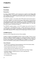
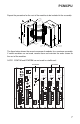
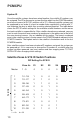
DIP Setting For SYS ID
Zone #'s S1 S2 S3 S4
Master 1 - 9 0 0 0 0
1 10 - 18 1 0 0 0
2 19 - 27 0 1 0 0
3 28 - 36 1 1 0 0
4 37 - 45 0 0 1 0
5 46 - 54 1 0 1 0
6 55 - 63 0 1 1 0
7 64 - 72 1 1 1 0
8 73 - 81 0 0 0 1
9 82 - 90 1 0 0 1
10 91 - 99 0 1 0 1
1 = On 0 = Off
ID
SYS
S1
S2
S3
S4
10
Satellite Zones & SYS ID Switch Positions
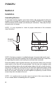
System ID
Once the satellite systems have been wired together, the satellite ID numbers can
be assigned. The ID for the master system (the one which has the PCMTIM module)
must be set to zero (all SYS ID switches set to "0"). Although satellite systems can
be numbered in any order, it is best to number them sequentially, starting with "1"
and following the way in which they are daisy-chained together. The table below
shows the SYS ID switch settings for the available satellite numbers and the zones
that each satellite is responsible for. After satellites have been numbered, you may
want to mark the actual zone numbers for each zone in the white area to the left of
the zone terminal screws. Use an indelible felt-tip marker. The lowest numbered
zone in the satellite system is the top zone in the PCMZPM module adjacent to the
PCMCPU module. The highest zone in the satellite is the bottom zone in the last
PCMZPM module.
After satellite systems have been wired and ID numbers assigned, the system can
be powered up. If it is necessary to change the ID number of a satellite after the
system has been powered, you must remove and then reapply power TO THAT
SATELLITE after changing switch settings.
PCMCPU
Satellite