
Programming instructions


12
PCMCPU
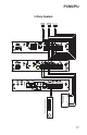
One-Way Paging System with Satellites
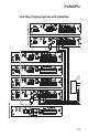
The illustration on the next page shows the wiring between different assemblies in
a system with satellites for one-way paging. Four pairs of audio wires are daisy-
chained between adjacent assemblies. These pairs are for the high-power paging
and background music (PA OUT and RT and HPBGM IN and RT), and the low-
power paging and background music (PA IN and RT & LPBGM IN and RT).
If a system is only using one type of paging, either all high-power or all low-power,
only two pairs of wires are needed to connect assemblies together. An all low-power
system would need only PA IN and RT and LPBGM IN and RT. Likewise, in an all
high-power system, the only inter-assembly wiring needed would be PA OUT and
RT and HPBGM IN and RT. The centralized high-power amplifier would still connect
to PA IN and RT and PA OUT and RT.
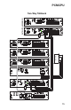
The DATA LINK RCA cable is also daisy-chained between assemblies. See the
section on Data Link wiring for suggested RCA cable types and wiring techniques
for multiple assembly systems. Although this diagram shows wiring between the
master and a satellite, the same wiring connections would exist between adjacent
satellite assemblies up to the maximum system of 10 satellites. Two stranded wires
can be clamped in each of the terminals to simplify wiring and eliminate wiring
splices.
NOTE: The Bogen PCM Configuration Guide contains more detailed
information on applications. It can be downloaded at:
www.bogen.com/products/pdfs/telephonepagepdfs/PCM2000c.pdf