
Programming instructions

6
Section 2
Installation
Assembling Modules
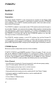
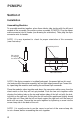
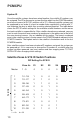
To assemble modules together, place them side by side starting with the left most
module of the assembly (for master system assembly, PCMCPU). Plug the ribbon
cable connector into its header (see drawing for orientation). Then plug the 6-pin
connector onto its header.
NOTE: It is very important to check for proper orientation of this connector
(see illustration).
NOTE: If the 6-pin connector is installed backwards, the power light on this mod-
ule (and possibly the entire assembly) will not light when powered up. Correct this
by separating the modules and locating the reversed 6-pin connector.
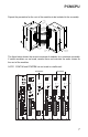
Place the modules close together and dress the connector cables away from the
sheet metal so that they will not get pinched. Push the two units together while
aligning the locking tabs on the top and bottom sides of the left unit with the lock-
ing slots on the right unit. At this point the left unit will be positioned slightly ahead
of the right unit. Now slide the left unit back against the right unit until the faces of
both units are even. Secure the two units together by tightening a screw into the
screw clamp tab in the back of the unit.
NOTE: It is usually easier to run the screw in and out of the screw clamp tab,
to cut a thread, before assembling the units together.
Align connectors
so locking ridge
faces header wall.
6-pin Connector
Align polarizing tab in slot
Ribbon Cable Connector
PCMCPU