
Programming instructions

8
Power
The PCM system requires 12V DC 1.5A. Use the PCMPS2 power supply. Plug the
power supply into the POWER jack on the PCMCPU module. Power can also be
connected to the 12V DC terminals on the connector block.
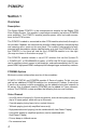
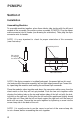
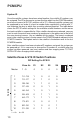
For a system with no satellites, set SYS ID DIP switches on PCMCPU module to
the position shown. See section on System Expansion in this manual for addi-
tional information on setting system IDs in expanded systems.
Zone #s
DIP Setting For SYS ID
S1 S2 S3 S4
Master 1 - 9 0 0 0 0
Program/Run Switch
The Program/Run switch must be set to the PROGRAM position during system
programming and the RUN position during normal operation. Refer to the instruc-
tions included with the PCMTIM module for programming instructions.
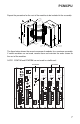
Audio Connections
Centralized amplifier connections are made to the screw terminals marked PA IN
and PA OUT on the PCMCPU module. Connect PA IN and RT (return) to the audio
input on the paging amplifier. Connect the high-power (70V) output of the amp to
the PA OUT and RT terminals.
Low-Power BGM
Connect BGM source to the LPBGM IN & RT terminals (Connect signal ground or
shield to RT terminals and the hot to IN). This provides low-level BGM signals to the
PCMZPM modules with LO PWR OUTPUT selected. This input is unbalanced.
High-Power BGM
Connect BGM source to the input of a 70V amplifier. Connect the high-power (70V)
output of the amplifier to the HPBGM IN & RT terminals (amplifier common should
connect to RT). This provides high-power background music signal to the PCMZPM
modules with HI PWR OUTPUT selected.
Emergency/Shift Change Trigger
External input control is available to trigger a tone signal from the PCM2000 over
the paging system. Shorting EM/SC to the GND terminal will produce a user-
programmed tone into a preselected group of zones. See Programming section of
the PCMTIM manual for information on programming the EM/SC feature.
AUX/GND Contacts
These contacts are used to synchronize with an external master clock. Shorting these
terminals resets the real time clock in the PCMTBM module to a user preset time. See
the PCMTIM manual Programming section for further information on this function.
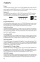
ID
SYS
S1
S2
S3
S4
10
PCMCPU
System ID