PCM2000 Configuration Guide © 2012 Bogen Communications, Inc. All rights reserved. Specifications subject to change without notice.
Contents SECTION I - APPLICATION CONFIGURATIONS ............................................................................................................................4-31 Configuration 1: Page Port Contact Closure/3-Zone/One-Way Paging/Single Amplifier/25 & 70V AC Speakers Setup Drawing........................................................................................................................................................................4 Description .....................................
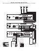
CONTACT CLOSURE 70V PBX PAGING PORT 4 1 - Not used COM R T 2 - Contact Closure 3 - Dry audio (R) 4 - Dry audio (T) 5 - Contact Closure 6 - Not used R T BOGEN PAGING AMPLIFIER SETTINGS PCM TIM 0 1 - SYS ID - + RT - GND - 1.
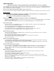
CONFIGURATION 1: PAGE PORT CONTACT CLOSURE / 3-ZONE / ONE-WAY PAGING / SINGLE AMPLIFIER / 25 & 70V AC SPEAKERS In this configuration, the PCM unit responds to a contact closure on pins 2 & 5 of the TRUNK/PAGE PORT jack on the PCMTIM module shorting the +5V source to its ground. When the closure is removed, the page ends. Audio is provided to the system through a separate pair of leads on pins 3 & 4 of the TRUNK/PAGE PORT jack on the PCMTIM module. Pins 1 & 6 are not used in this configuration.
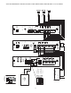
70V PBX PAGING PORT 6 1 - Not used COM R T 2 - Contact Closure 3 - Dry audio (R) 4 - Dry audio (T) 5 - Contact Closure 6 - Not used R T BOGEN PAGING AMPLIFIER SETTINGS PCM TIM 0 1 - SYS ID - + RT GND - 1.
CONFIGURATION 2: PAGE PORT VOX CIRCUIT / 3-ZONE / ONE-WAY PAGING / SINGLE AMPLIFIER / 25 & 70V AC SPEAKERS This configuration is for Page Ports without Contact Closures. A dry audio pair connected to pins 3 & 4 of the TRUNK/PAGE PORT jack on the PCMTIM module is used to detect audio and activate the system. Paging ends when the VOX timer or default timer times out. Pins 1, 2, 5 & 6 are not used in this configuration. Note: The audio pair (page port) must pass DTMF in order to select a zone.
70V 1 - Not used COM R T 2 - Contact Closure 3 - Dry audio (R) 4 - Dry audio (T) 5 - Contact Closure 6 - Not used R T BOGEN PAGING AMPLIFIER PBX (LOOP START TRUNK) SETTINGS PCM TIM 0 1 - SYS ID - + RT - GND - 1.
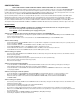
CONFIGURATION 3: LOOP START TRUNK / 3-ZONE / ONE-WAY PAGING / SINGLE AMPLIFIER / 25 & 70V AC SPEAKERS In this configuration, the PCM unit supplies a 48V talk battery and loop current detection from pins 3 & 4 of the TRUNK/PAGE PORT jack on the PCMTIM module to the loop start trunk in the telephone system. There are two modes of operation for loop start trunk. (1) When the unit detects a loop resistance between TIP and RING, it activates. When the loop opens, the page ends.
70V 1 - Not used COM R T 2 - Contact Closure 3 - Dry audio (R) 4 - Dry audio (T) 5 - Contact Closure 6 - Not used R T BOGEN PAGING AMPLIFIER PBX (GROUND START TRUNK) SETTINGS PCM TIM 0 1 - SYS ID - + RT + - EM/SC GND - 1.
CONFIGURATION 4: GROUND START TRUNK / 3-ZONE / ONE-WAY PAGING / SINGLE AMPLIFIER / 25 & 70V AC SPEAKERS In this configuration, the PCM unit supplies a 48V talk battery and loop current detection from pins 3 & 4 of the TRUNK/PAGE PORT jack on the PCMTIM module to the ground start trunk in the telephone system. There are two modes of operation for ground start trunk. (1) When the ground start trunk grounds Ring, the unit responds by closing the connection to Tip, which completes the access procedure.
70V R T 12 COM R BOGEN PAGING AMPLIFIER 1 - Not used T 2 - Contact Closure 3 - Dry audio (R) 4 - Dry audio (T) 5 - Contact Closure 6 - Not used PBX (STATION ACCESS CENTREX) SETTINGS PCM TIM 0 1 - SYS ID - + RT + - EM/SC GND - 1.
CONFIGURATION 5: STATION LEVEL/CENTREX / 3-ZONE / ONE-WAY PAGING / SINGLE AMPLIFIER / 25 & 70V AC SPEAKERS In this configuration, the PCM unit responds to a 90V AC 20Hz ringing signal in pins 3 & 4 of the STATION/90V NGT RNG jack on the PCMTIM module and answers after the first full ring. As soon as it answers, the default timer is started. The default timer determines the maximum length of any page. When a paging zone is selected, the VOX timer (if enabled) is started.
PCM TIM 0 1 BOGEN PCM CPU SYS ID IN HI PWR 14 70V COM R BOGEN PAGING AMPLIFIER T MASTER ASSEMBLY RD COM - 1.
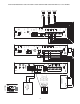
CONFIGURATION 6: EXTENDED PAGING SYSTEM This illustration shows the wiring between a master assembly and a satellite assembly in a PCM system with a satellite assembly for one-way paging. The required setup for one-way basic configuration includes: PCMTIM, PCMCPU, PCMZPM, and the power supply PCMPS2.
R 16 T 70V BOGEN PAGING AMPLIFIER COM PCM TIM + PCM PS2 0 BOGEN PCM CPU 1 SYS ID OUT PA IN + RT - 1.5 A + 12VDC GND RT IN PA ZONE C ZONE B ZONE A LOCAL BGM OUTPUT RD COM RD C RD B RD A - GND RT + EM/SC AUX IN HI PWR LO PWR GLOBL BGM ZONE C ZONE B RT HPBGM LPBGM VOLUME POWER ZONE A ZONE B ZONE C ZONE A - BGM + OFF NOISE REDUCTION DELAY OUT OFF ON TALKBACK RT PA LPBGM PA + - ON TALKBACK VOLUME POWER PCM ZPM IN OUT RT IN RT IN 12 VDC 1.
CONFIGURATION 7: TWO-WAY TALK BACK PAGING SYSTEM This configuration is essentially the same as the one-way paging system described previously. The main difference between the oneway configuration and this configuration is that the centralized high-power amplifier is connected to the PCMTBM module instead of the PCMCPU module. The required setup includes: PCMTIM - PCMCPU - PCMTBM - PCMZPM - PCMPS2. Modules must be assembled, from left to right, in this order.
PCM TIM 0 1 BOGEN PCM CPU SYS ID OUT PA IN IN HI PWR LO PWR 18 IN RT - 1.
CONFIGURATION 8: TWO-WAY TALK BACK EXTENDED PAGING SYSTEM This configuration is essentially the same as the two-way paging system described previously on page 17. The main difference is the addition of a satellite assembly. The required setup includes: PCMTIM - 2 PCMCPU - PCMTBM - 4 PCMZPM - 2 PCMPS2 Note: Talk Back is only available in High-Power Zones with 25 & 70V AC speakers. The paging access output from the telephone system must support two-way communications.
SETUP FOR CONFIGURATION 9: 3-ZONE / ONE-WAY PAGING / LOW-POWER SYSTEM / SELF-AMPLIFIED SPEAKERS 20
CONFIGURATION 9: 3-ZONE / ONE-WAY PAGING / LOW-POWER SYSTEM / SELF-AMPLIFIED SPEAKERS Low-Power System is a switch-selectable feature that allows the system designer to use self-amplified speakers on the zone outputs. The PCMZPM module that is to be used as a low-power module will switch only low-level signals to the zone outputs for use with dedicated amplifiers or self-amplified speakers. Note that its output switch is set to LO PWR. Note: Low-Power Systems do not support two-way paging.
SETUP FOR CONFIGURATION 10: 6 ZONES / ONE-WAY PAGING / MIXED HIGH- AND LOW-POWER ZONES / 25 & 70V AC SPEAKERS 22
CONFIGURATION 10: 6 ZONES / ONE-WAY PAGING / MIXED HIGH- AND LOW-POWER ZONES / 25 & 70V AC SPEAKERS High- and Low-Power Mixed System is a non-programmable feature that lets the system designer use a dedicated amplifier or self-amplified speaker per zone and at the same time use a centralized amplifier for zones requiring less than 250 watts of power*.
COM 600 25V 70V - + MIC INPUT 24 VOL MIC VAR1 DELAY EMERGENCY MICROPHONE SENS VOX RELAY AUDIO OUTPUT BOGEN G R MIC 6 CONDUCTOR MODULAR CABLE Contact closure Dry audio input to PCMTIM (from VAR1) Not used Not used Dry audio input to PCMTIM (from VAR1) Contact closure RJ 11 MODULAR BOX Y BK LINE BL W PRS40C PCM TIM SETUP FOR CONFIGURATION 11: MICROPHONE OVERRIDE
CONFIGURATION 11: MICROPHONE OVERRIDE Microphone Override is a feature that lets the system designer take priority over all paging functions and make a system-wide page to all speakers. In addition to the PCM modules, setup requires a Bogen VAR1 (voice-activated relay), PRS40C (12V DC power supply) and an MBS1000A or DDU250 (desktop microphone). The Override feature includes a quad beep pre-announce tone which can be enabled or inhibited.
0 1 0 STATION GND START CONF TN VOX DIS 1-RNG DLY IGNORE TRNK TMER 2 3 4 5 6 7 TRUNK MODE LOOP START PRE ANN TN VOX ENABLE ANS IMMED DETECT CPC NO TIMER 1 9 ON MIN MAX TIME TIME PAGING TIME DFT120 8 1
CONFIGURATION 12: DFT120 & TAMB2 WIRING DIAGRAM / GROUND START TRUNK OR STATION LEVEL In this configuration, the telephone output is connected to the Bogen Telephone Access Module model TAMB2; the TAMB2 module is connected to the Bogen Digital Feedback Terminator model DFT120; and the DFT120 is connected to the PCM2000 system. The TAMB2 module is activated by the telephone system and, at the same time, the DFT120 is activated by the TAMB2ʼs normally open contacts.
VMIX LEVEL COM T4 T3 T2 T1 TNG1S 28 6 CONDUCTOR MODULAR CABLE Contact closure Dry audio input to PCMTIM (from ProHold) Not used Not used Dry audio input to PCMTIM (from ProHold) Contact closure NORMALLY OPEN CUSTOMER SUPPLIED SWITCH PCM TIM SETUP FOR CONFIGURATION 13: EMERGENCY ALERT TONES
CONFIGURATION 13: EMERGENCY ALERT TONES Emergency Alert Tones is a non-programmable feature that lets the caller take priority over all paging functions and send an emergency alert tone to all speakers. In addition to the PCM2000 modules, this option requires a Bogen VMIX (8-channel mixer/pre-amplifier), an input/output module RIO1S, and a Tone Generator module TNG1S.
CONFIGURATION 14: SINGLE AMPLIFIER BACKGROUND MUSIC LINE-LEVEL SIGNAL Single amplifier BGM operation is a programmable feature that lets the PCM2000 use the paging amplifier to provide high-power BGM to the 25/70V AC speakers when the paging system is idle.
CONFIGURATION 15: RELAY DRIVER OUTPUT ZONE A ZONE B ZONE C OFF ON TALKBACK SUPPRESSION DIODES SUPRESSION DIODES POWER LPBGM VOLUME BGM OUT IN RELAY ZONE A ZONE B ZONE C GLOBL BGM RELAY LO PWR OUTPUT HI PWR RELAY IN RT LOCAL BGM + ZONE A + ZONE B + ZONE C RD A RD B RD C POWER SUPPLY 12VDC + RD COM - Each PCMZPM module has three relay driver outputs - RD A, RD B, and RD C - one for each speaker zone.
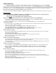
SECTION II - PROGRAMMING SYSTEM PROGRAMMING System programming lets you set certain PCM options and tone features using the DTMF keys of a telephone. It also lets you program paging zone groups and signaling zone groups. All programming is accomplished through the TRUNK/P/P jack on the PCMTIM module regardless of the telephone interface used.
FEATURE CODES AND DEFAULTS Feature Privacy Beep Inhibit Enable Pre-announce Tone Inhibit Beep Chime Confirmation Tone Inhibit Enable Emergency O/R Tone Inhibit Enable All-Call Inhibit Enable Dialing Time-out Inhibit Enable Trunk Disconnect Inhibit Enable 1 Amp BGM Inhibit Enable Default Timer VOX Timer Zone Group Feature Code Additional Data Default 006 007 Enable 003 004 005 Chime 001 002 Enable 008 009 Inhibit 010 011 Enable 012 013 Enable 014 015 Inhibit 018 019 Inhibit 050 051 *01 0
Feature Clock Set Clock Sync.
Feature Time Trigger 6 Zone Group Inhibit Enable 2-Second Tone 3-Second Tone 4-Second Tone 5-Second Tone 6-Second Tone 7-Second Tone 8-Second Tone Chime Time Trigger 7 Zone Group Inhibit Enable 2-Second Tone 3-Second Tone 4-Second Tone 5-Second Tone 6-Second Tone 7-Second Tone 8-Second Tone Chime Time Trigger 8 Zone Group Inhibit Enable 2-Second Tone 3-Second Tone 4-Second Tone 5-Second Tone 6-Second Tone 7-Second Tone 8-Second Tone Chime Reset Default Setup Tone (in Program Mode Only) Turn On Turn Off Fea
SYS-ID SWITCH SETTINGS CHART FOR ADDITIONAL SATELLITE SYSTEMS Zone #ʼs S1 S2 S3 S4 1-9 0 0 0 0 1 10-18 1 0 0 0 2 19-27 0 1 0 0 3 28-36 1 1 0 0 4 37-45 0 0 1 0 5 46-54 1 0 1 0 6 55-63 0 1 1 0 7 64-72 1 1 1 0 8 73-81 0 0 0 1 Master Satellite 9 82-90 1 0 0 1 10 91-99 0 1 0 1 36
APPENDIX Align polarizing tab in slot Module Assembly Align connectors so locking ridge faces header wall. LOCKING TAB LOCKING TAB LOCKING SLOT ALIGN CONNECTORS SO LOCKING RIDGE FACES HEADER WALL 6-pin Connector Ribbon Cable Connector ALIGN POLARIZING TAB IN SLOT SCREW CLAMP TAB & SLOT LOCKING TAB LOCKING SLOT STEP 1: Assembling Modules PCMTIM to PCMCPU and to PCMZPM (see Illustration above) • • • • • • Plug the 6-pin power connector from the PCMCPU module to the PCMTIM module jack (J2).
NOTES 38
NOTES 39
50 Spring Street, Ramsey, NJ 07446 U.S.A. Tel. 201-934-8500 • Fax 201-934-983 www.bogen.