
Specifications


7
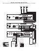
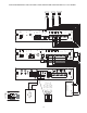
CONFIGURATION 2:
PAGE PORT VOX CIRCUIT / 3-ZONE / ONE-WAY PAGING / SINGLE AMPLIFIER / 25 & 70V AC SPEAKERS
This configuration is for Page Ports without Contact Closures. A dry audio pair connected to pins 3 & 4 of the TRUNK/PAGE PORT jack
on the PCMTIM module is used to detect audio and activate the system. Paging ends when the VOX timer or default timer times out.
Pins 1, 2, 5 & 6 are not used in this configuration.
Note: The audio pair (page port) must pass DTMF in order to select a zone.
The required setup includes: PCMTIM - PCMCPU - PCMZPM - PCMPS2. Modules must be assembled, from left to right, in this order.
INSTALLATION:
STEP 1: Assemble Modules PCMTIM to PCMCPU and to PCMZPM (see Illustration/Instructions on Appendix page 37,
then return to this page and complete the following Steps).
Note: DO NOT connect the PCMPS2 (power supply) at this point.
STEP 2: Connecting Paging Port/VOX from the Telephone System to the PCMTIM Module
• Take the page port (VOX) audio pair from the telephone system and wire it to the RJ11 TRUNK/PAGE PORT jack in the PCMTIM
module to pins 3 & 4 (red and green).
• Use a 4- or 6-pin modular cord to connect the RJ11 to the TRUNK/PAGE PORT jack on the PCMTIM module.
STEP 3: Switch Settings
• Set the slide switches on the PCMTIM module for Page Port VOX Configuration: Set the first switch to VX (for VOX)
and set the second switch to P/P (for Page Port).
• Set the SYS-ID DIP switches on the PCMCPU module to the OFF position (to the left).
• Set the RUN-PROGRAM switch on the PCMCPU module to the RUN mode (up).
• Set the Talk Back DIP switches on the PCMZPM module to the OFF position (to the left) for all zones.
• Set the OUTPUT switch on the PCMZPM module to the HI-PWR position (down).
STEP 4: Testing your System
• Connect power supply PCMPS2 to the PCMCPU module to either the power jack 12V DC input or wire it to the 12V DC
screw terminals observing polarity.
• At this point all the power LEDs should be lit on each module.
• Access the page port from the phone system and verify access tones (double beep) in handset.
• At this point, the system should be functioning properly.
• Disconnect Power Supply.
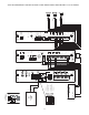
STEP 5: Connecting the Paging Amplifier
• Locate the terminals on the PCMCPU module labeled PA IN/RT and wire to the TIP and Ring (T & R) input on the Bogen
paging amplifier (either TPU-Series, GS-Series, or Classic Series amplifiers).
• Locate the terminals on the PCMCPU module labeled PA OUT/RT and wire to COMMON and either the 25 or 70V output
on the paging amplifier.
STEP 6: Connecting 25 & 70V AC Speakers
• Locate the terminals on the PCMZPM module labeled ZONE A. These terminals have two connections marked + and - .
Wire your speakers for ZONE ONE to these terminals. Observe polarity (-) to common (+) to selected tap setting.
• Follow the same procedure for the terminals labeled ZONE B for ZONE TWO, and the terminals labeled ZONE C
for ZONE THREE.
STEP 7: Testing your System
• Connect the power supply PCMPS2 to the PCMCPU module to either the power jack 12V DC input or wire it to
the 12V DC screw terminals, observing polarity.
• Connect the Bogen amplifier to the AC power outlet (120V AC, 60Hz).
• Set the volume on your Bogen amplifier to a 1/2 turn.
• Access the paging from the telephone system and listen (on the handset) for the confirmation tone (double beep).
• Dial 01 to access ZONE ONE and listen (on the handset and also to the speakers) for a pre-announce tone (single beep)
followed by your page (audio).
• Follow the same steps for ZONES TWO (02) and THREE (03). Dial [00] for All-Page.
• Set the Bogen amplifier to the desired volume level.