
Specifications
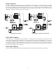

17
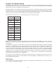
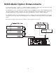
Internal Jumper Selections
Internal jumpers are provided for phantom power (MIC1/MIC2), Telco Page/MIC 2 input selection, monitor speak-
er muting, and privacy tone defeat.
Warning: High voltages are present within the MCP35A. The unit should not be operated without covers in place.
To change jumpers, unplug the MCP35A and remove it from the enclosure. Remove the top cover and place the
jumper in the desired position. Replace the top cover and plug the unit back in.
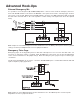
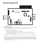
Phantom Power
To enable phantom power for MIC 1, place J1 in the ON position.
To enable phantom power for MIC 2, place J2 in the ON position
Telco Page/MIC 2
Jumper J3 selects the TELCO PAGE input jack or the MIC 2 input terminals for the telephone page function. Place
the jumper in the MIC 2 position when using the MIC 2 terminals for emergency paging applications using a
microphone. Place the jumper in the TELCO position when using the TELCO PAGE input for paging applications.
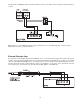
MIC 1/Console Mic
1. Locate and loosen the two screws securing the jumper link on the rear chassis terminal strip connecting
MIC 1 HI terminal to the CONS MIC terminal.
2. Move the link away from the CONS MIC terminal.
3. Connect a balanced or unbalanced low-impedance microphone to the MIC 1 terminals. Connect the
cable shield to the GND terminal.
4. Move the shunt on J4 to the OFF position to disable the monitor speaker muting feature when the MIC 1
push-button is selected.
Note: J1 should be in the OFF position when the console mic is connected to the MIC 1 input.
Privacy Tone Defeat
Shunt J5 enables/disables the supervisory tone feature. Move the shunt to the OFF position to disable the super-
visory tone.
Note: When the privacy tone is disabled, a short 1 second audio interruption will be noticed every 15 seconds
when intercom communication is in progress.