MCP35A Master Control Panel Installation & Use Manual Specifications subject to change without notice. © 2010 Bogen Communications, Inc. All rights reserved.
NOTICE: Every effort was made to ensure that the information in this guide was complete and accurate at the time of printing. However, information is subject to change. WARNING: To reduce the risk of Fire or Electric Shock, Do Not Expose this apparatus to rain or moisture. Apparatus shall not be exposed to dripping or splashing and no objects filled with liquids, such as vases shall be placed on the apparatus. WARNING: Only connect unit to AC mains outlet providing protective earthing connection.
Table of Contents Introduction..................................................................................................................2 Unpacking ....................................................................................................................2 Front & Rear Panel Connection Diagrams ................................................................3 Installation....................................................................................................................
Introduction The Bogen Model MCP35A Master Control Panel provides facilities for instantaneous two-way communication and distribution of emergency pages, background music or other program material to speaker-equipped locations. The control panel has two built-in amplifiers. The intercom amplifier, rated at 20 watts, features a frequency response shaped for maximum intelligibility.
Front & Rear Panel Connection Diagrams 1 9 Front Panel 2 3 4 5 6 1. Console MIC - Used for intercom and emergency page functions. Normally 7 8 6. Program/Talk Level - LED Indicators: N (normal) lights green to indicate proper signal level; P (peak) lights amber to indicate higher than normal signal level; O (overload) lights red to indicate possible signal clip. configured (via terminal link) as microphone 1.
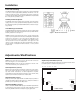
Installation Power and Grounding The MCP35A Master Control Panel operates from a 120 volt, 60Hz AC source and consumes approximately 100 watts. The AC line cord is terminated in a thee-prong plug, and should be plugged into a three-wire grounded outlet providing nominal 120 volts, 60 Hz AC. It is important that the control panel be grounded properly. Auxiliary Power Receptacle An 840-watt, three-wire grounded outlet is provided on the rear panel to supply power to accessory equipment.
Gain Adjustments (Rear Panel) Remote Emergency Microphone Paging (Rear Panel) Screwdriver-adjustable INPUT GAIN controls are accessible via the rear panel for MIC 1, MIC 2, AUX, Tel Page, Talk, and Listen. Set the controls so that signal clipping cannot occur. The MIC 2 input may optionally be used in place of the Telco Page input for use with a remote microphone (internal jumper). Figure 5 shows the connection of the MBS1000A to the MIC 2 terminals.
Associated Equipment SBA225 Room Selector Panel SCR25A Call-In Module Bogen Model SBA225 Room Selector Panels are capable of connecting up to 25 speaker-equipped locations to a PROGRAM, INTERCOM channel, or off. Each unit provides 25 lever-action, three-position, four-pole selector switches with positive detents, and red LED indicators. Caution: The installation of accessory equipment requires the removal of protective covers; exposure of internal components presents an electrical shock hazard.
TWK351 Option Appendix The TWK351 option permits light call-in on 2-conductor shielded cable. See Figure 7 for wiring diagram. General Wiring Where possible, locate the MCP35A centrally, relative to the rooms being served, in order to minimize the length of speaker cables. Orient the unit so that the operator, program director, or other parties are able to see the controls at all times. Provide adequate lighting and ventilation.
Call Switches and Speakers Call/Privacy Option Flush-mounted switches require single-gang outlet boxes. Install outlet boxes about four feet from the finished floor, in a location which will allow personnel easy access to the switch for call-in and/or communicating via the room speaker. Wall-mounted speakers should be installed at a recommended height of 7-1/2 feet above the finished floor.
Figure 11– Schematic Diagram, SBA225 Room Selector Panel Figure 12– Typical Interconnection Diagram Figure 13– Typical Wiring Diagram 9
Technical Specifications Rated Output Program Intercom Frequency Response Program Intercom Distortion 35W RMS 20W RMS +1,-3 dB from 80 Hz to 15 kHz Shaped for maximum intelligibility Less than 1% @ RPO and bandwidth Inputs Two Lo-Z balanced microphones; Hi-Z unbalanced AUX; TELCO PAGE; 25V BOOSTER Output 25V balanced line Controls Front Panel Rear Panel Internal Tone Specifications Power Requirements Dimensions Weight Optional Equipment: Program Selection: MIC 1, MIC 2, AUX Level: MONITOR/LISTEN, PR