User’s guide
ADDENDUM TO BOGEN MODEL PM3180 NOTE: Model PM3000 has been discontinued. SAFETY INFORMATION NOTICE: Every effort was made to ensure that the information in this guide was complete and accurate at the time of printing. However, information is subject to change. WARNING: To reduce the risk of Fire or Electric Shock, Do Not Expose this apparatus to rain or moisture. Apparatus shall not be exposed to dripping or splashing and no objects filled with liquids, such as vases shall be placed on the apparatus.
Models PM-3000 & PM-3180 User’s Guide Part No.
© 1996 Bogen Communications, Inc. 50 Spring St., Ramsey, NJ 07446 Warning: Changes or modifications to this unit not expressly approved by the party responsible for compliance could void the user’s authority to operate the equipment.. All rights are reserved. No part of this document may be photocopied, reproduced, or translated to another language without the prior written consent of Bogen Communications Inc.
Models PM-3000 & PM-3180 User’s Guide Owner’s Information Model Number Serial Number_________________________ Date of Purchase______________________ Place of Purchase_____________________ Address______________________________ ____________________________________ iii
Contents Unpacking . . . . . . . . . . . . . . . . . . . . . . . . . . . . . . . . . . . . . .1 Packing List . . . . . . . . . . . . . . . . . . . . . . . . . . . . . . . . . . . .1 Accessories . . . . . . . . . . . . . . . . . . . . . . . . . . . . . . . . . . . .1 Conventions . . . . . . . . . . . . . . . . . . . . . . . . . . . . . . . . . . . .1 Introduction . . . . . . . . . . . . . . . . . . . . . . . . . . . . . . . . . . . . .2 Description . . . . . . . . . . . . . . . . . . . . . . . . . . . . . .
Unpacking Packing List The ProMatrix carton contains the following components: 1 - ProMatrix unit 1 - Removable Control Panel* 1 - Wireless Infrared Remote Controller 2 - AAA Batteries 1 - 25-foot Control Panel Cable 1 - AC Power Cord 2 - Wall Anchors 1 - User Manual 1 - Product Registration Card *The control panel must be connected to the amplifier chassis prior to operation. See page 4 to install control panel. Accessories A front panel mount kit and rack mount kit are available for this product.
Introduction Description The ProMatrix products are designed for sound reinforcement/distribution in multi-room applications. The PM-3180 consists of three independent amplifiers, rated at 20, 60 and 100 watts. The PM-3000 is a three channel preamplifier unit designed to offer the flexibility for applications with power requirements that exceed the limits of the PM-3180. Both units have a programmable interface that lets you selectively assign priority levels to inputs and custom configure features.
Introduction Features The ProMatrix units have the following features: • 2 Lo-Z balanced Mic inputs (Mic A is female XLR, Mic B is screw terminals). Mic B can be configured as a 600-Ohm transformer balanced input for telephone paging applications. • Automatic level control for Mic inputs. • Choice of microphone precedence activation (VOX, Normally Open, Normally Closed). • Phantom power for use with condenser microphones. • 4 Aux inputs (RCA unbalanced).
Quick Start This Quick Start section is intended to assist you in getting the ProMatrix unit up and running quickly so that you can become familiar with it. Important: Do not place any objects directly on top of the unit. Leave at least 2 inches of space above the unit to assure proper ventilation. When locating the PM-3180, be sure to leave at least 2 inches of space on the right side of the unit to allow for fan exhaust.
Quick Start Basic Wiring 1. Temporarily set the AUX INPUT TRIM controls on the rear panel to their full counterclockwise position. Trims will be adjusted later. 2. Be sure that the voltage select switch is set correctly. Connect the power cord to the AC LINE INPUT 3. Connect outputs. For the PM-3000, connect the correct style output (balanced or unbalanced) to the input of the external amp or other signal processing equipment. Refer to page 15 for wiring balanced or unbalanced outputs.
Quick Start Factory Programmed Configuration When the ProMatrix unit is first powered up, the factory default settings are loaded. The factory default priority table is listed below. If you want to change any of these priority levels, you will have to use the ASSIGNMENT function in the programming mode. See the Programming section of these instructions (Page 22) to set priority levels.
Quick Start Basic Operation This section will show you how to: • • • • • • • Apply power to the unit Understand the Control Panel (See page 12 for full description) Select which channel the control panel affects Change volume Change Bass and Treble response Manually select an input or allow priority-based switching Adjust Aux Input Trim Controls To Apply Power to the Unit Important Note: For PM-3000, make sure any power amplifiers connected to the unit are off when the unit is first plugged in.
Quick Start To Control Volume Note: Changing any of the volume, bass or treble levels will effect all inputs associated with that amp/channel channel. Turning up the volume for the current amp/channel will cause other inputs assigned to that amp/channel to play louder when they become active. Likewise for bass and treble. Be sure VOL is the current control (this is the normal default function). If BASS or TREB are lit, press the VOL button.
Quick Start To Select a Specific Input The ProMatrix unit is normally set to monitor input activity and, based on the default or installer-created priority table, automatically switches the proper input for each amp/channel. You can override the priority switching feature of any amp/channel to select a specific input to be on continuously. 1. Press the AUTO button. Its indicator LED will flash. and the alphanumeric display will show SEL INPUT. 2.
Quick Start Aux Input Trim Adjustment By adjusting the Trim controls as follows, inputs with different signal levels are set approximately equal within the ProMatrix unit. Important: You must properly set the Aux Input Trim Controls. Improperly adjusted trims can result in high distortion levels, poor volume balance between different inputs or false triggering of inputs. To adjust trims, follow the procedure below: 1.
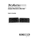
Rear Panel Model PM-3000 6 7 1 2 3 4 5 8 9 10 11 1. MIC A — Female XLR-type connector for balanced, LO-Z microphone input. Pin 1 is Gnd. 2. MIC B/TEL B — Screw terminal Input for Lo-Z balanced microphone. Software configurable as a 600Ω transformer coupled paging interface. 3. MIC PREC — Microphone precedence terminals for contact closure activation. 4. AUX INPUT — Unbalanced input jacks (RCA type) for program sources. 5. AUX INPUT TRIM — Variable attenuators for adjusting input source levels. 6.
Rear Panel Model PM-3180 8 1 2 3 4 5 6 7 9 10 1. MIC A — XLR-type connector for balanced, LO-Z microphone input. Pin 1 is Gnd. 2. MIC B/TEL B — Input for Lo-Z balanced microphone. Software configurable as a 600Ω transformer coupled paging interface. 3. MIC PREC — Microphone precedence terminals for contact closure activation. 4. AUX INPUT — Unbalanced input jacks (RCA type) for program sources. 5. AUX INPUT TRIM — Variable attenuators for adjusting input source levels. 6.
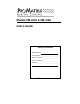
Front Panel 1 7 6 AUXA 9 2 10 3 8 4 5 1. Alphanumeric display area. 2. AUX A/B/C/D — Input selector buttons & indicators. 3. AUTO — Controls manual or automatic input selection. 4. POWER — Applies power to the ProMatrix unit. 5. AMP 1/2/3 — Amp/Preamp Channel Selector Buttons. 6. Level control Arrow buttons. 7. LED pointer area. 8. PROG, NEXT, BACK, ENT & EXIT — Programming buttons. 9. MIC A/MIC B — Microphone input selector buttons. 10. VOL/BASS/TREB — Function control selector buttons.
Infrared Remote Controller The infrared remote controller provides all of the functions of the front panel. Before using the controller, install two AAA-size batteries in the battery compartment of the controller. Be sure to observe correct polarity. To use the controller, point the controller at the infrared receiver window on the left side of the front panel of the ProMatrix chassis and press the desired button. 1. POWER — Controls power to the ProMatrix unit. 2.
Wiring Information Outputs For PM-3000 Preamplifier Each preamplifier channel has its own balanced output terminals and unbalanced RCA output jacks on the rear panel to handle different amplifier and signal processing inputs. 1 2 1. This figure shows wiring from the PM-3000 Balanced Output to a standard XLR-type of balanced amplifier input. 3 Note 1 Note 1. In some instances, connecting the cable shield to both the PM-3000 ground and the amplifier’s input ground may cause ground loops.
Wiring Information Outputs For PM-3180 Amplifier Each amplifier channel has its own output terminal strip on the rear panel. Each terminal strip can handle a different type of speaker load. All amps can handle 70V & 25V distributed or 8-Ω or 4-Ω loads. The 70V, 25V and 8-Ω outputs are transformer-coupled. The 4-Ω output is directly connected to the amplifier output. The 4-Ω output provides a wider fre8-Ω Load quency response with better bass reproduction and lower distortion.
Wiring Information AUX Inputs Unbalanced input sources other than microphones are connected to the AUX INPUT jacks. The output lead from the source must be terminated in an RCA-type plug. The input signal range is 100mVrms to 3Vrms and is adjusted using the AUX TRIM controls. Unbalanced audio source (CD/Tape/Tuner/Etc. Aux Input Trim Controls See page 10 for adjustment procedure Audio Process Link Wiring (PM-3180 Only) Typical Audio Process Link wiring is illustrated below.
Wiring Information MIC Inputs Mic A 2 1 Pin 1 is GND Pin 2 (+) Pin 3 (-) 3 If Mic A has a push-to-talk switch, use these terminals for the switch connection (see Mic Precedence Setup in the Programming Section). Mic B Shield Push-to-talk switch pair. Normally open or normally closed (see Mic Precedence Setup in Programming Section). MBS-1000 Mic B/Tel T PBX Page Port or Paging Adapter R * X *Switch closure available on some page ports.
User Operation The ProMatrix Control Panel The control panel is the interface between the user and the unit functions. Since there are three channels (amp or preamp) and only one control panel, the ProMatrix uses selector buttons, indicators and an alphanumeric display to provide control of the overall functions. The information below will familiarize you with the operation of the control panel.
User Operation To Control Volume, Bass or Treble Note: Changing any of the volume, bass or treble levels will effect all inputs associated with that amplifier channel. Turning up the volume for the current amplifier will cause other inputs to play louder when they become active. Likewise for bass and treble. 1. To control volume, bass, or treble you must first select the desired control (VOL, BASS, TREB so that its indicator LED lights. The LED pointer will light to indicate the approximate level setting.
User Operation the current input was lowered by. This is because the levels set by the user are temporary and the ProMatrix always strives to maintain volume differences set by the preset programming. Typically, this will only occur when the inputs or limits are set vastly different for the inputs assigned to an amp channel. The same applies to the tone controls where the amp tries to maintain the EQ differences.
Programming Enter Programming Mode The programming mode lets the installer custom configure the ProMatrix unit. The installer uses the programming buttons on the front panel or the infrared remote controller. Programming Buttons 1. Press PROG. The LED next to the button lights and the display shows 3 dashes. The unit requires a 3-digit password. The factory default is 0 0 0. 2. Press the NEXT or BACK buttons to increment or decrement the first flashing digit position until “0” appears and then press ENT.
Programming Programming Menu The ProMatrix programming menu is illustrated below: Press PROG 000 (or user-selected password) Assignment Set priority level for each amplifier-input combination Microphone Set precedence activation, ALC, phantom power Set Mic B for telephone input Presets Preset volume, bass and treble levels Vol limit Limit maximum volume for each amp-input combination Inhibit Inhibit users ability to make volume or tone adjustments Aux Mute Set mute level of Aux inputs during mi
Programming Assignment The ASSIGNMENT function lets you assign a priority levels to each amplifier-input combination. This function lets you create a variety of configuration schemes and obtain maximum versatility to meet application needs.
Programming 5. Select a level and press ENT to save the selection (PROG LED will blink when selection has been entered). Important: You must press ENT after every change you make in order to save the new setting. This is true for all programming procedures. 6. Repeat Step 3, 4 and 5 to assign any other inputs to the amplifier channel. Note that priority level numbers become unavailable from the selection list as they are assigned to a particular input.
Programming Mic Set Up This function lets you set the Microphone features: • Precedence Activation: N.O. = Normally Open - requires short between precedence terminals to activate mic N.C. = Normally Closed - requires short between precedence terminals to deactivate mic VOX = Voice Activated switch activation) • Automatic Level Control (ALC) • Phantom Power (PPS) • For MIC B, it also permits setting the input as a transformer-balanced 600-Ohm input for telephone paging applications.
Programming 4. The display shows A ALC ON indicating that MIC A ALC status is ON. A ALC ON 5. Press the NEXT or BACK buttons to select ON or OFF. 6. Press ENT to store the selection. 7. The display shows A PPS OFF indicating that the MIC A phantom power is OFF. If Mic B is set as a TEL input (see below), PPS will not be shown since it does not apply to tel inputs. A PPS OFF 8. Press the NEXT or BACK buttons to select ON or OFF. 9. Press ENT to store the selection.
Programming Presets This feature lets the installer adjust the power-up volume, bass and treble of each amp/channel-input combination. It also sets the relative volume levels between different inputs on a particular amplifier channel. The same inputs can have different volume and EQ settings on different amps. Note: The system should be completely wired before making any of these adjustments, since the installer will normally want to listen to the output in order to make the adjustment.
Programming Note: Press and hold arrow buttons to effect rapid changes in volume. Quick presses of the buttons will effect single-step changes in volume. 5. Once you have set the desired volume for an input, press ENT. The PROG light will blink to indicate that the data was stored. 6. At this point, you can select another amp/channel-input combination and repeat Steps 4 and 5 to set other volume levels. You can also select the BASS or TREB control and set the levels for these controls.
Programming Volume Limit This function sets the maximum volume level that a user can select for an amp/channel-input combination. Warning: The Volume Limit function will cause the ampinput combination in the PM-3180 to play at the maximum limit (default value is 25, full volume). This will normally be quite loud. Be careful that people are not next to speakers and that the power rating of the speakers is high enough to handle full amplifier power.
Programming 6. Once you have set the desired limit for an input, press ENT. The PROG light will blink to indicate that data was stored. 7. Select another amp/channel-input combination and repeat Steps 4 and 5 to set other levels. Remember to press ENT after setting each level. 8. Once all levels are set, press EXIT to return to the function menu. At this point you can exit the programming mode or press the NEXT/BACK buttons to select another function.
Programming Inhibit This function lets the installer inhibit the user’s ability to change the preset volume and tone settings for a particular amplifier (Bass and Treble are always inhibited together as Tones. Pressing BASS or TREB does the same thing). Once set, the unit will not respond to commands from the front panel or remote controller for this amplifier channel in the user mode. 1. Enter programming mode and press the NEXT or BACK buttons until INHIBIT appears on the display. 2.
Programming Aux Mute The Aux Mute allows paging over music. This function sets the volume level of each AUX input when a page is made. Upon completion of the page, the music level fades up to the previous level. The levels can be set differently for each Aux input on each amplifier. Note: The system should be completely wired before making any of these adjustments, since the installer will normally want to listen to the output in order to make the adjustment. 1.
Programming Amplifier Link (PM-3180 Only) This function disconnects the power amplifier input from the preamp processing circuit and permits the addition of outboard signal processing equipment (such as an equalizer or ambient noise response unit) to the Audio Process RCA connectors on the rear of the amplifier chassis. The link is illustrated graphically below: 1. Enter programming mode and press the NEXT or BACK buttons until AMP LINK appears on the display. 2. Press ENT to enter the function.
Programming Password This function lets the installer change the program mode password. 1. Enter programming mode and press the NEXT or BACK buttons until PASSWORD appears on the display. 2. Press ENT to enter the function. The display shows the the current 3-digit password (The default is 0 0 0.) The first numeral will be flashing. PSWRD 000 3. Press the NEXT or BACK buttons to increment the first numeral from 0 to 9. 4. Press ENT to store the selection. 5. The second numeral flashes.
Programming Labels This function lets you modify the names displayed for the current input source during user operation. For example, you can change the name of AUX A to TAPE. 1. Enter programming mode and press the NEXT or BACK buttons until LABELS appears on the display. 2. Press ENT to enter the function. The display shows AUXA or a previously entered label. The first character will be flashing. AUXA 3. If desired, select another input by pressing the appropriate button. 4.
Programming Factory Defaults This function lets you quickly erase all current configuration programming and return the amplifier to its out-of-box configuration. 1. Enter programming mode and press the NEXT or BACK buttons until DEFAULTS appears on the display. 2 Press ENT to enter the function. The display shows: CLR ALL NO, referring to Clear All (stored programming)? = No. CLR ALL NO 3. Press the NEXT/BACK buttons to toggle between NO or YS (for YES). 4. Press ENT to confirm the selection. 5.
Testing & Troubleshooting Testing Assignment Test: Remove all audio sources from Aux inputs. Connect an active audio source to the lowest priority input for the current amp/channel. Move the active source through the inputs in the order of priority that was previously set. Result: The input source should immediately change as the audio source is moved between inputs. If the unit delays in switching between aux inputs then the priority schedule is set differently than expected.
Testing & Troubleshooting Vol Limit Test: Manually select an Aux or Mic input. Press and hold the right arrow button until the display stops incrementing. Result: The display stops incrementing at the volume limit for the particular input and amp combination (see page 30). Turn the Promatrix power off and then on to return volume levels to their initial preset levels. Troubleshooting Display shows COM ERROR or a series of 0, +, X • Unplug the unit, wait 5 seconds then restore power.
Testing & Troubleshooting Mic never active • Check that the type of precedence setting is correct for the application (See page 26). • If mic is a condenser type, check that phantom power is applied to mic input (see page 27) • Check that mic is assigned to the amp in question (see page 24). • If Mic B is the problem, check that it is not set for Tel operation (see page 27). Mic distorted • Reduce volume until output is not distorted. • Check if ALC for that mic is turned on (see page 27).
Getting Help Bogen has support available in case you have a problem with your ProMatrix. In order to make the most effective use of this service, please be sure to fill out and return the product registration card included with this unit. Best results are obtained when you: • Read the User’s Guide before operating • Remember that certain functions can be “locked out” when the amplifier is in operation. • Ensure all input and output wiring is correctly installed.
Specifications PM-3180 Power Output: Amp 1: 100 wrms Amp 2: 60 wrms Amp 3: 20 wrms Output Taps: 8-ohms, 25V and 70V transformer-coupled (balanced or unbalanced) 4-ohms direct coupled (unbalanced) Output Regulation: <2dB from no load to full load (all amps) Input Sensitivities: Mic Inputs: 750µVrms (no ALC) Aux Input: 100mVrms to 2.
Specifications PM-3000 Outputs: 0dBV balanced outputs via screw terminal strips (all channels) 0dBV unbalanced outputs via RCA jacks (all channels) Maximum Output: 15dBV into 600Ω balanced Maximum Gain: 17.7dB (Vol. control @ 25) Input Sensitivities: Mic Inputs: 750µVrms (no ALC); Tel Input: 170mVrms; Aux Input:100mVrms to 2.
Spring Street • Ramsey, NJ 07446 www.bogen.