
Installation Instructions

Model RMPWMK3
Installation Instructions
Introduction
The RMPWMK3 provides a secure and attractive means to remotely mount the ProMatrix™ Models PM3000
and PM3180 control panels. The mounting kit can accommodate single-gang box mounting or mounting
directly to the surface of a wall. User-supplied 6-conductor interconnect cable can be routed either in wall or
surface mounted. This kit includes the cable adapters necessary for connecting the user-supplied cable to the
main ProMatrix unit.
Contents of Kit:
1 - Sub-bracket 6 - Wire nuts
1 - Mounting plate 4 - Sheet metal screws (black, 3/8”)
1 - Modular telephone block 4 - Wall anchors and screws
1 - 6-feet modular telephone cord 2 - Machine screws (6-32 X 3/4”)
Step 1. Cable Size & Routing
The RMPWMK3 requires user-supplied 6-conductor cabling from the mounting location of the control panel to
the location of the main unit. A modular telephone jack and 6-foot telephone cable complete the connection to
the main unit.
Once the necessary cable length is known, use the table below to determine the minimum conductor gauge to
use.
Note: Route the cable away from electrically noisy items like large motors, transformers,
fluorescent ballasts and light dimmer circuits.
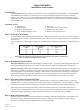
Step 2. Mounting the Sub-bracket
Gang-box mounting: Position the sub-bracket as shown in Figure 1. Route the cable through the large hole
in the sub bracket and use two (2) 6-32 X 3/4” machine screws to attach the sub bracket to the gang box.
Surface mounting: Position the sub bracket against the wall in the desired mounting location (see Figure 1 for
the correct orientation of the sub bracket). Make sure that the sub bracket is level and mark the location of the
4 mounting holes in the sub bracket. Install the 4 wall anchors in these locations and mount the sub bracket.
Fish the cable through the large hole in the sub bracket if in-wall wiring is used. If using surface-mounted
cable, make sure the cable will line up with the notch in the mounting plate and is secured to the wall.
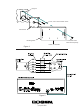
Step 3. Wire and Attach the Mounting Plate
Write the colors of the conductors of the user-supplied cable in the spaces provided in Figure 2. Using the
supplied wire nuts, make connections to the wires on the black mounting plate as shown on Figure 2. Double
check the connections to ensure that they are secure and that they match the colors written in Figure 2.
Using the 4 black sheet metal screws (3/8”), attach the mounting plate to the sub bracket (see Figure 1).
Check that the mounting plate is level. There is play in both the sub bracket holes and mounting plate holes to
allow some leveling adjustment. Snap the ProMatrix control panel onto the wall mount assembly.
Step 4. Main Unit Connections
Mount the modular telephone block so that the 6-foot telephone cable will reach the main unit telephone con-
nector on the back. Again follow Figure 2 and connect the cable wires to the modular telephone block.
Connect the modular telephone cable between the unit and the block.
Wire Gauge Wire Resistance Max. Cable Length
(AWG) (
ΩΩ
/1000ft) (feet)
26 40 100
24 25 160
22 16 250
54-5027-01
Printed in U.S.A. 9706