TPU250 Telephone Paging Amplifier Installation and Use Manual © 2000 Bogen Communications, Inc. All rights reserved.
© 2000 Bogen Communications, Inc. All Rights Reserved. Printed in Korea. Notice Every effort was made to ensure that the information in this guide was complete and accurate at the time of printing. However, information is subject to change. Important Safety Information Always follow these basic safety precautions when installing and using the unit: 1. Read and understand all instructions. 2. Follow all warnings and instructions marked on the product. 3.
Contents Page INTRODUCTION ..........................................................................................................................4 PACKAGE CONTENTS..............................................................................................................4 INSTALLATION..............................................................................................................................5 Mounting ...................................................................................
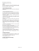
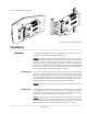
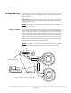
Telephone Paging Amplifier POWER PEAK LEVEL APHEX TREBLE BASS VOX RINGER VOLUME MUSIC MUTE MUSIC VOLUME MODEL TPU250 250 WATT AMPLIFIER MIC VOLUME TEL VOLUME BOGEN COMMUNICATIONS ALC APHEX MUSIC MUTE + MIC BAL MUSIC IN GND TEL BRIDGING MUSIC IN GND CONTACT RING T TEL RING R 70V 25V COM GND Figure 1: Telephone Paging Amplifier Introduction This document describes the Bogen TPU250 250-watt Telephone Paging Amplifier (see Figure1).
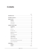
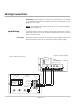
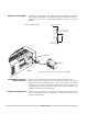
Figure 2: Wall Mounting the Amplifier SCREW #8 x 5/8" (M4 x 16 mm) WITH TEFRON WASHER 1/8 x 5/16 (3 x 8 MM) TYP 4 PCS WER L PO VE AK LE PE HEX AP LE EB TR SS BA .... X VO ER RING ME LU VO UTE CM SI MU ME LU VO IC MUS .... .... .... .... .... .... .... .... . .... .... ME LU MIC WER PO VO ME LU L L VO VE LE TE X AL AK PE C HE AP LE EB TR SS BA .... X VO ME .... .... LU .... VO ER RING .... .... . E MUT IC MUS ....
Wiring Connections IMPORTANT: Before making any connections or wiring changes to the amplifier or any equipment connected to the amplifier, make sure that the amplifier is NOT plugged into an AC outlet. NOTE: The amplifier does not have a power switch, so it must be unplugged in order to turn the power off. Input Wiring All signal input and control wiring is made to the terminal strip and RCA connectors beneath the left side access cover.
Music Input A single RCA connector and screw terminals are provided for the connection of a background music source.The music input is a mono unbalanced input, so the music source’s output should be unbalanced and mono. If a balanced input is needed, use a Bogen Line-Matching Transformer WMT1A (sold separately) to balance the music input.The WMT1A is also effective in breaking ground loops that cause hum. Microphone Input A high gain, low impedance microphone input is provided in this amplifier.
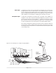
Night Ringer Connection Either a standard telephone (analog) ring signal (90 - 105 V AC, 20 - 30 Hz) or an external contact closure activates the night ringer function of the amplifier. To activate the night ringer using standard telephone (analog) ring, connect the analog station's tip lead to the TEL RING "T" terminal and connect the ring lead to the "R" terminal. If using an external contact closure, connect the closure pair across the CONTACT RING terminals (not polarized).
Output Wiring All output wiring connections are made to the terminal strip located under the right side access panel. Loosen the 2 Phillips-head screws on each side of the cover and remove the cover. IMPORTANT: Before making any connections or wiring changes to the amplifier or any equipment connected to the amplifier, make sure that the amplifier is NOT plugged into an AC outlet. NOTE: The amplifier does not have a power switch, so it must be unplugged in order to turn the power off.
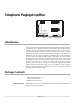
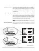
Additional Power Amplifier An external power amplifier can be used with the TPU250 amplifier. You must first add a resistor voltage divider to the telephone amplifier, as illustrated in Figure 8. Connect a patch cord to the high-level/high-impedance input of the booster amplifier. TO 25V OUTPUT TERMINAL Figure 8 : Output Circuitry 39K 1/2 W TO HI-Z INPUT OF BOOSTER AMPLIFIER 10K 1/2W TO COM ON TERMINAL STRIP RCA Jack ABLE ... .. EPT CC G A ... .. IRIN 2W SS ... .. CLA . .... T-..
Operation IMPORTANT: Before plugging the amplifier into an AC outlet, turn all volume controls to their full counterclockwise positions. Indicators POWER IND The POWER IND LED illuminates whenever AC power is applied to the amplifier (there is no power switch on the amplifier). PEAK LEVEL The PEAK LEVEL LED illuminates whenever the speaker output signal level approaches its maximum level. This indicator is used when setting volume levels.
BASS and TREBLE Bass and treble controls are provided to adjust the high frequency and low frequency response of the paging system. Reference positions are provided for these controls. When set to these positions, the frequency response of the system will be flat. Set the controls to the customer’s satisfaction. Clockwise rotation increases (boosts) the response and counterclockwise reduces (cuts) the response. Increasing bass and/or treble can cause output signal peaks to increase.