
User Guide

7
TPU600-G2
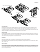
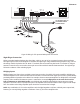
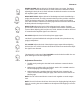
Figure 6: Bridge Inputs
100-240 VAC
+ –
MIC
INPUT
+ NC –
MUSIC INPUT
+ –
MUTE
CONTACT
RING
TEL
RING
70V, 25V, 8-OHM
+ –
TEL
INPUT
IN OUT
– +
G
G
G
G G
BRIDGE
BAL LINE OUT
G R
RING T
100-240 VAC
+ –
MIC
INPUT
+ NC –
MUSIC INPUT
+ –
MUTE
CONTACT
RING
TEL
RING
70V, 25V, 8-OHM
+ –
TEL
INPUT
IN OUT
– +
G
G
G
G G
BRIDGE
BAL LINE OUT
G R
RING
T
Output Wiring Connections
All output wiring connections are made to the rear panel. Loosen the two Phillips-head screws on each side of the
Phoenix-style plug to connect speaker wiring (see Figure 6).
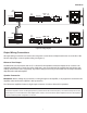
Balanced Line Output
The Balanced Line Output (BAL LINE OUT) is a line-level low-impedance balanced output that can connect to an
outboard amplier input. It carries the same signal that is sent to the inboard TPU amplier, but includes the gain
settings and controls of the TPU preamp. Any volume changes necessary for the Balanced Line Output should be
adjusted at the outboard amplier.
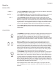
Speaker Connection
IMPORTANT: Before making any connections or wiring changes to the amplier, or any equipment connected to the
amplier, make sure that the amplier is NOT powered on.
The TPU600-G2 ampliers feature a single output connector for 8-ohm, 25V, and 70V speakers.
NOTICE
The minimum impedance of this 70V/8Ω high-impedance system should not be less than 8Ω (ohms). The combined total power of each
speaker tap must not exceed 80% of the rated amplier power. Failure to observe minimum speaker impedance will cause the amplier to
self-protect until the speaker conguration is corrected.