OWNER’S MANUAL Tiller/Edger SAFETY FIRST! Before operating this equipment, read this Owner's Manual and the separate manual supplied by the engine manufacturer.
SAFETY RULES CAUTION: ALWAYS DISCONNECT SPARK PLUG WIRE AND PLACE WIRE WHERE IT CANNOT CONTACT SPARK PLUG TO PREVENT ACCIDENTAL STARTING WHEN SETTING UP, TRANSPORTING, ADJUSTING OR MAKING REPAIRS. • Wear approved safety glasses when operating this equipment. The operation of any powered machine can result in foreign objects being thrown by high-speed rotating parts. • Do not till near underground electric cables, telephone lines, pipes, or hoses.
SAFETY RULES • Stop the engine, disconnect the spark plug wire and prevent it from touching the spark plug whenever you leave the equipment, before unclogging the tines, or when making any repairs, adjustments or inspections. • Take all possible precautions when leaving the machine unattended. Always stop the engine. Disconnect the spark plug wire and prevent it from touching the plug. • Before cleaning, repairing, or inspecting, stop the engine and make certain all moving parts have stopped.
CONGRATULATIONS on your purchase of a Tiller/Edger with Edger Attachment. It has been designed, engineered and manufactured to give you the best possible dependability and performance. Should you experience any problems you cannot easily remedy, please contact your nearest authorized dealer or the Factory. Please read and retain this Manual. The instructions will help you assemble and maintain your machine properly. Always observe the “SAFETY RULES.” WARNING TO AVOID INJURY: • READ THE OPERATOR’S MANUAL.
INDEX (CONTINUED) Decals . . . . . . . . . . . . . . . . . . . . . . . . . . . . . . . . . . . . . . . . .16 Edging . . . . . . . . . . . . . . . . . . . . . . . . . . . . . . . . . . . . . . . . .12 Engine Air Filter . . . . . . . . . . . . . . . . . . . . . . . . . . . . . . . . . . . . .14 Carburetor . . . . . . . . . . . . . . . . . . . . . . . . . . . . . . . . . . .14 Cleaning . . . . . . . . . . . . . . . . . . . . . . . . . . . . . . . . . . . . .14 Engine On-Off Switch . . . . . . . . . . . . . . .
CONTENTS OF HARDWARE PACK Parts bag contents (not shown full size) (1) Border/Edger Wheel (2) Bushings for Narrow Width Tilling (1) Short Bushing for Border/Edger Parts packed separately in carton (not shown full size) (1) Border/Edger Tine ASSEMBLY Read these instructions in their entirety before you attempt to assemble or operate your new equipment. The Border Edger Attachment does not need to be installed until you are ready to do edging projects (refer to instructions in this Section).
ASSEMBLY height setting holes. If this height is correct for you, simply tighten the two handlebar knobs. If a higher setting is desired, reposition the handlebar knobs, mounting screws and washers in the other set of holes. • Check the locations of the three plastic ties (C, Figure 1). The ties must be positioned as shown. NOTE: There is just one handlebar storage position – folded over the engine as originally shipped.
ASSEMBLY • Install the short bushing (D, Figure 4) on the right-hand or left-hand tine shaft. Then place the Border/Edger wheel (C) on the same shaft – the wheel hub should face toward the tiller. Insert the ring lock pin through the rounded side of the tine shaft and snap the ring down over the shaft (see “DETAIL”, Figure 4). • Slide the long bushing (B) on the opposite side shaft. Then install the Border/Edger tine (A) and secure it with the ring lock pin.
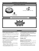
OPERATION KNOW YOUR EQUIPMENT READ THIS OWNER’S MANUAL AND ALL SAFETY RULES BEFORE OPERATING YOUR EQUIPMENT. Know the location and function of all features and controls on the equipment. Save this manual for future reference. Engine On-Off Switch (A, Fig. 5-Engine Detail) Move switch to ON prior to starting engine. Move switch to OFF to stop the engine.
OPERATION PRE-START PREPARATION Before starting the engine, perform the following checks and services: • Disconnect the spark plug wire from the spark plug. • Put the engine On-Off switch in the OFF position. • Check that all wires and cables are properly and securely connected. It is very important that the three plastic cable ties (J, Figure 5) be positioned as shown. The control cables must not be kinked or jammed in the handlebar.
OPERATION Priming When Cold Starting: Use this priming method to start the engine after it has been sitting or has been in brief storage, and has fuel in the tank. Use the Standard-Volume Priming Position (Figure 6) and push in top of primer bulb two (2) times for above 550F, or three (3) times if below 550F. When Warm Starting: Do not use the primer to restart the engine after it has been stopped after running, still has fuel in the tank, and has not cooled completely.
OPERATION Tips and Techniques WARNING • Adjust engine speed to suit the tilling conditions. Remember that the rotating tines help to pull the machine forward. Use slower speeds and a shallow depth setting when learning to use the unit and whenever you are tilling on hard, rough or uneven ground. • The amount of pressure applied to the handlebars helps to control tilling depth.
MAINTENANCE/SERVICE REQUIRED MAINTENANCE SCHEDULE WARNING Before inspecting, cleaning or servicing the machine, shut off engine, let all moving parts come to a complete stop, disconnect the spark plug wire and move the wire away from the spark plug. Failure to follow these instructions can result in personal injury or property damage. Note (1) – After first five (5) hours of use. Note (2) – Clean daily when conditions are extremely dusty or dirty.
MAINTENANCE/SERVICE Engine Air Filter Primer Bulb Primer Line Idle Speed Screw (Silver) Idle Mixture Screw (Black) Fuel Line It is very important that air filter service be performed according to the maintenance schedule. Refer to the separate Engine Owner’s Manual for inspection and cleaning instructions. IMPORTANT: Never run engine without air filter assembly properly installed.
MAINTENANCE/SERVICE • Slide one of the long bushings (provided with unit) onto the shaft. See Figure 17. Insert the ring lock pin through the rounded side of the tine shaft and snap the ring down over the shaft (see DETAIL, Figure 4, in the Assembly Section). • Repeat on the opposite side of the machine. STORAGE WARNING • Never store your equipment when there is a fuel mixture in the fuel tank.
TROUBLESHOOTING GUIDE PROBLEM POSSIBLE CAUSE Engine does not start. CORRECTIVE ACTION 1. Spark plug wire disconnected. 1. Reconnect wire to spark plug. 2. Out of gas/two-cycle oil fuel mixture. 2. Check fuel tank. Add fuel mixture. 3. Stale fuel mixture. 3. Drain old mixture. Add fresh mixture. 4. Priming procedure not correct. 4. Refer to priming instructions and starting procedure in manual. 5. Dirty air filter(s). 5. Clean or replace air filters. 6. Worn, corroded or broken spark plug. 6.
REPAIR PARTS – Model 12207 2 13 21 19 7 5 A 22 18 6 18 A B A 23 24 B 9 3 B 10 1 4 A 13 A 8 20 14, 15 5 3 16, 17 24 22 23 14, 15 11, 12 22 TRANSMISSION ASSEMBLY Ref # Part # 1 2 1915039 1915040 3 4 5 6 7 8 1983632 1918307 1983731 1983636 1983637 1904416 9 10 11 1909923 1185741 1111600 Description Transmission Case - left-side. (Incl. pressed-in bushing) . . . . . . . . . . . . . Transmission Case - right-side. (Incl. pressed-in bushing) . . . . . . . . . . . . . Oil Seal . .
REPAIR PARTS – Model 12207 7 4 9 5 42 SEE PREVIOUS PAGE 6 49 42 13 1 48 46 47 13 8 45 16 44 20 45 15 44 18 14 13 17 21 18 19 42 37 35 36 31 19 42 32 38 24 27 34 43 23 39 25 33 41 40 26 28 22 40 29 30 18
REPAIR PARTS – Model 12207 Ref # Part # 1 2 4 5 6 7 8 9 13 14 15 16 17 18 19 20 21 22 23 24 25 26 27 28 29 1918303 1909936 1918221 1917451 1918123 1750608 1731025 1909775 1763682 1918120001 1918121001 1909720 1983663 1107381 1817146 * 1909487 1918310 1918336 1917249 1917248 1917250 1186292 1186387 1100241 Description Handlebar Assy. (Incl. Refs. 4 & 5) . . . . . . . . Decal - On/Off Ignition Switch . . . . . . . . . . . Decal - Throttle Lever Operation . . . . . . . . . . Handlebar Grip, PVC . . . . . . .
CUSTOMER SERVICE INFORMATION Owner Registration Card Please fill out and mail the enclosed owner registration card. The purpose of this card is to register each unit at the factory in order to keep the owner informed with informational bulletins and safety literature. Customer Service and Technical Service If you have questions or problems with the unit, contact your local dealer or the factory. (When calling or writing, provide the Model/Serial Numbers of the unit.