OPERATOR’S MANUAL SNOW THROWER Models 642E, 642F, 662E, 614E, 644E, 664F, & 6A4E Model 664 Shown IMPORTANT: READ SAFETY RULES AND INSTRUCTIONS CAREFULLY Warning: This unit is equipped with an internal combustion engine and should not be used on or near any unimproved forestcovered, brush-covered or grass-covered land unless the engine’s exhaust system is equipped with a spark arrester meeting applicable local or state laws (if any).
TABLE OF CONTENTS Content Page Important Safe Operation Practices ...................................................................3 Hardware Pack...................................................................................................5 Assembling Your Snow Thrower ........................................................................6 Know Your Snow Thrower..................................................................................10 Operating Your Snow Thrower........................
SECTION 1: IMPORTANT SAFE OPERATION PRACTICES This symbol points out important safety instructions, which if not followed, could endanger the personal safety and/or property of yourself and others. Read and follow all instructions in this manual before attempting to operate this machine. Failure to comply with these instructions may result in personal injury. When you see this symbol—heed its warning.
5. 6. 7. 8. 9. 10. 11. 12. 13. 14. 15. 16. 17. 18. 19. 20. Never run an engine indoors or in a poorly ventilated area. Engine exhaust contains carbon monoxide, an odorless and deadly gas. Do not operate machine while under the influence of alcohol or drugs. Muffler and engine become hot and can cause a burn. Do not touch. Exercise extreme caution when operating on or crossing gravel surfaces. Stay alert for hidden hazards or traffic.
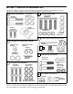
SECTION 2: CONTENTS OF HARDWARE PACK Lay out the hardware according to the illustration below for identification purposes. Part numbers are shown in parentheses. (Hardware pack may contain extra items which are not used on your unit.
SECTION 3: ASSEMBLING YOUR SNOW THROWER NOTE: References to right or left side of the snow Handle Panel thrower are determined from behind the unit in the operating position. The “operator’s position” is defined as standing directly behind the snow thrower, facing the handle panel. Left Bracket Unpacking • • • Carriage Bolts Remove staples or break glue on top flaps of the carton. Remove any loose parts included with unit (i.e., operator’s manual, etc.).
2” Hex Bolt Auger Control Saddle Left Bracket Left Handle Hex Lock Nut Spacer Cable Roller Guide Lock Washers Hex Bolt 3/4” Hex Bolt Handle Panel Figure 6 Attaching Shift Rod (Hardware D) “Z” Fitting • Figure 4 • • • • • • Repeat process for the right side Traction Control. Lay handle assembly behind snow thrower. See Figure 5. Insert a hex bolt 3/4” long and lock washer through the lower hole on the bottom of the handle.
• Models 614, 644, 664, and 6A4: Thread the ferrule onto the shift rod, up or down the shift rod and align with the far hole on the narrow side of the shift lever assembly behind the handle panel. See Figure 8. Flat Washer Auger Drive Clutch • • • Traction Drive Clutch Shift Lever Ferrule • • Hairpin Clip IMPORTANT: The cable should have very little slack, but should NOT be tight. An overtightened cable may prohibit the auger and drive from disengaging.
NOTE: Lock nuts cannot be threaded onto a bolt by hand. Tighten with two 7/16” or adjustable wrenches. Carriage Bolts Attaching The Chute Directional Control (Hardware C) • Thread one hex nut about halfway onto eye bolt on the chute directional control. • Insert eye bolt through the hole provided in the left handle. See Figure 11. • Secure with cupped washer (cupped side against the handle) and other hex nut. Do not tighten until after attaching the other end of the chute directional control.
SECTION 4: KNOW YOUR SNOW THROWER Traction Control WARNING: Read, understand, and follow all instructions and warnings on the machine and in this manual before operating. The traction control is located on the right handle. Squeeze the traction control grip to engage the wheel drive. Release to stop. Shift Lever Chute Directional Control The shift lever is located in the center of the handle panel. The shift lever may be moved into one of six positions.
Safety Ignition Key condition of the ground from where snow has to be removed. See Figure 14. The safety ignition key must be fully inserted in the switch before the unit will start. Remove the ignition key when the snow thrower is not in use. See Figure 14. Throttle Control The throttle control is located on the engine. It regulates the speed of the engine and will shut off the engine when pushed down completely. See Figure 14 IMPORTANT: Do NOT attempt to turn the key.
pushing. Additional priming may be necessary for first start if temperature is below 15 degrees Fahrenheit. • • To Engage Augers • • Grasp starter handle and pull rope out slowly, until it pulls slightly harder. Let rope rewind slowly. Pull starter handle rapidly. Do not allow handle to snap back. Allow it to rewind slowly while keeping a firm hold on the starter handle. As engine warms up and begins to operate evenly, rotate choke knob slowly to OFF position.
Chute Clean-out Tool If your unit is not equipped with drift cutters, contact Customer Support as instructed on page 2 for information regarding price and availability. The chute clean-out tool is conveniently fastened to the rear of the auger housing with a mounting clip.
SECTION 6: MAKING ADJUSTMENTS WARNING: Never attempt to make any Frame Cover adjustments while the engine is running, except where specified in operator’s manual. Tire Pressure (Pneumatic Tires) • The tires are overinflated for shipping purposes. Before operating check tire pressure and reduce pressure to between 15psi and 20 psi. NOTE: If the tire pressure is not equal in both tires, the unit may pull to one side or the other.
Chute Assembly WARNING: If any adjustments need to be made to the engine while the engine is running (e.g. carburetor), keep clear of all moving parts. Be careful of muffler, engine and other surrounding heated surfaces. The distance snow is thrown can be adjusted by changing the angle of the chute assembly. To do so, stop the engine by removing the ignition key and loosen the plastic wing knobs found on either side of the discharge chute.
Both Wheels Driving • IMPORTANT: NEVER operate the snow thrower with the click pin inserted through both the RIM and the OUTSIDE HOLE in the axle. Doing so can result in serious damage to the drive system. Rotate wheel assembly to align hole in the hub with the inner hole on the axle shaft. Insert klick pin in the hole. Outer axle shaft hole should be visible.
SECTION 8: SERVICING YOUR SNOW THROWER WARNING: Before servicing, repairing, • or inspecting, disengage all clutch levers and stop engine. Wait until all moving parts have come to a complete stop. Disconnect spark plug wire and ground it against the engine to prevent unintended starting If the augers will not turn, check to see if the bolts have sheared. Replacement shear bolts and hex lock nuts have been provided with the snow thrower.
Drive Belt Auger Belt Friction Wheel Disc Drive Pulley Friction Wheel Drive Belt Idler Pulley Support Bracket Stop Bolt Engine Pulley Idler Pulley Figure 28 Friction Wheel Rubber Figure 26 • Reassemble auger drive belt(s) by following instructions in reverse order. Replace the friction wheel rubber if any signs of wear or cracking are found. Follow instructions below to replace the rubber. Drive Belt • • • Follow first four steps of previous instructions.
If unit is to be stored over 30 days, prepare for storage as follows: Screws Friction Wheel Rubber • Hub • • Friction Wheel Plates NOTE: Fuel stabilizer is an acceptable alternative in minimizing the formation of fuel gum deposits during storage. Do not drain carburetor if using fuel stabilizer. Figure 30 • • Remove gasoline from carburetor and fuel tank to prevent gum deposits from forming on these parts and causing possible malfunction of engine.
SECTION 9: TROUBLE SHOOTING GUIDE Trouble Possible Cause(s) Corrective Action Engine fails to start Fuel tank empty, or stale fuel. Fill tank with clean, fresh gasoline. Fuel will not last over thirty days unless a fuel stabilizer is used. Clean fuel line. Move switch to ON position Clean, adjust gap or replace. Insert key. Connect spark plug wire. Refer to the engine manual. Open fuel shut-off valve. Engine runs erratic Loss of power Engine overheats Excessive vibration Blocked fuel line.
Notes 21
Models 642E, 642F, 662E, 614E, 644E, 664F, & 6A4E 40 8 7 6 9 5 10 38 39 11 3 12 9 2 1 4 14 21 7 20 8 15 18 6 16 13 29 30 31 32 7 34 13 18 19 22 23 37 26 33 24 13 33 6 28 36 16 27 37 32 6 7 33 25 33 31 32 30 6 35 36 32 22 17 16
Models 642E, 642F, 662E, 614E, 644E, 664F, & 6A4E REF. NO. 1. 2. 3. 4. 5. 6. 7. 8. 9. 10. 11. 12. 13. 14. 15. 16. 17. 18. 19. 20. 21. 22. 23. 24. 25. PART NO. 712-0116 756-0178 784-5632B 710-0459A 741-0475 736-0242 712-3010 712-0324 736-0463 705-5226 731-1379C 710-0703 710-0451 738-0281 736-0167 712-3068 732-0611 736-0119 05931A 741-0309 684-0039D 684-0040D 684-0041D 684-0055C 736-0169 712-0798 784-5580 784-5581A REF. NO.
Models 642E, 642F, 662E, 614E, 644E, 664F, & 6A4E 17 16 18 17 1 8 16 20 2 3 5 19 22 27 26 4 20 55 25 18 23 9 19 28 54 7 11 10 21 12 29 30 13 38 39 54 15 24 24 53 40 55 14 6 7 41 39 34 23 42 43 35 7 23 37 36 44 29 47 45 46 51 50 48 49 52 24
Models 642E, 642F, 662E, 614E, 644E, 664F, & 6A4E REF. NO. 1. 2. 3. 4. 5. 6. 7. 8. 9. 10. 11. 12. 13. 14. 15. 16. 17. 18. 19. 20. 21. 22. 23. 24. 25. 26. PART NO. 712-0116 732-0193 736-0105 784-5619A 710-0459A 710-0788 714-0104 720-0232 711-0677 726-0100 747-0921 720-0201A 705-5204A 747-0697 735-0234 684-0008A 720-0274 705-5233A 705-5234A 750-1032 735-0199A 746-0778 705-5275 712-0429 736-0119 712-3010 705-5274 749-0910C REF. PART NO. NO. 27. 710-3103 28. 710-0262 29. 684-0105 684-0145 684-0106 30.
Models 642E, 642F, 662E, 614E, 644E, 664F, & 6A4E 20 27 39 46 Drive Clutch Cable 42 37 5 13 7 1 11 38 6 10 40 Auger Clutch Cable 4 3 4 1 2 14 15 26 5 36 16 42 16” Wheels 42 13” or 15” Wheels 7 9 10 11 12 25 31 25 28 23 43 17 18 32 24 8 4 1 22 33 8 5 29 34 41 20 21 44 19 35 45 Blower Housing 30 1 26 1 Auger Clutch Cable
Models 642E, 642F, 662E, 614E, 644E, 664F, & 6A4E REF. NO. 1. 2. 3. 4. 5. 6. 7. 8. 9. 10. 11. 12. 13. 14. 15. 16. 17. 18. 19. 20. 21. 22. 23. 24. PART NO.
Models 614E 1 2 3 5 4 8 9 13 27 16 22 11 10 12 15 20 16 4 7 6 23 14 24 17 18 19 25 REF. NO. 1. 2. 3. 4. 5. 6. 7. 8. 9. 10. 11. 12. 13. 14. PART NO. 710-1652 731-1324 732-0339 710-0627 710-3005 05896A 748-0234 756-0985 754-0343 756-0984 736-0270 710-0230 756-0313 710-1245A 21 DESCRIPTION Hex Washer Screw 1/4-20 x.5 Belt Cover Extension Spring Hex Screw 5/16-24 x .75 Hex Cap Screw 3/8-16 x 1.
Models 642E, 642F, 662E, 614E, 644E, 664F, & 6A4E 1 2 26 4 3 5 9 8 10 21 20 12 11 20 21 5 20 7 6 22 23 14 13 24 16 25 18 19 REF. NO. 1. 2. 3. 4. 5. 6. 7. 8. 9. 10. 11. 12. 13. PART NO. 710-1652 731-1324 710-3005 732-0710 710-0627 05896A 748-0234 756-0987 754-0346 756-0986 736-0270 710-0230 756-0313 17 15 19 IMPORTANT: For a proper working machine, use Factory Approved Parts. V-BELTS are specially designed to engage and disengage safely.
MANUFACTURER’S LIMITED WARRANTY FOR: The limited warranty set forth below is given by MTD LLC with respect to new merchandise purchased and used in the United States, its possessions and territories. d. MTD LLC warrants this product against defects for a period of two (2) years commencing on the date of original purchase and will, at its option, repair or replace, free of charge, any part found to be defective in materials or workmanship.