BT1340G/1 BENCH LATHE OPERATION MANUAL
1. GENERAL SAFETY RULES FOR POWER TOOLS DO NOT ATTEMPT TO OPERATE UNTIL YOU HAVE READ THOROUGHLY AND UNDERSTAND COMPLETELY ALL INSTRUCTIONS, RULES, ETC. CONTAINED IN THIS MANUAL FAILURE TO COMPLY CAN RESULT IN ACCIDENTS INVOLVING FIRE, ELECTRIC SHOCK OR SERIOUS PERSONAL INJURY. MAINTAIN OWNERS MANUAL AND REVIEW FREQUENTLY FOR CONTINUING SAFE OPERATION, AND INSTRUCTING POSSIBLE THIRD-PARTY USER. READ ALL INSTRUCTIONS 1.1 KNOW YOUR POWER TOOL For your own safety, read the owner’s manual carefully.
1.2.9 WEAR PROPER APPAREL No loose clothing. Gloves, neckties, rings bracelets, or jewelry to get caught in moving parts. Nonslip footwear is recommended . Wear protective hair covering to contain ling hair. 1.2.10 ALWAYS USE SAFETY GLASSES Also use face or dust mask if cutting operation is dusty. Everyday eyeglasses only have impact – resistant lenses. They are not safety glasses. 1.2.11 SECURE WORK Use clamps or a vise to hold work when practical.
Feed work into a blade or cutter against the direction of rotation of the blade or cutter only . 1.2.20 NEVER LEAVE TOOL RUNNING UNATTENDED. TURN POWER OFF. Don’t Leave tool until it comes to a complete stop. The operation of any power tool can result in foreign objects being thrown into the eyes, which can result in severe eye damage . Always wear safety glasses or eye shields before using your Lathe . We recommend wide vision safety mask for use over spectacles , or standard safety glasses . 2.
DO ALLOW FAMILIARILY (GAINED FROM FREQUENT USE OF YOUR LATHE) TO BECOME COMMONPLACE. A CARELESS FRACTION OF A SECOND CAN ALLOW FOR SEVERE INJURY. 3.MACHINE SPECIFICATION Bench lathes are especially suitable for machining workshops, tool rooms and repairing workshops to machine shafts spindles, sleeves and disc workpieces of middle or small types. They can also be used to cut imperial, diameter and module threads. And with compact construction and reasonable composition, they can cut very well.
TECHNICAL DATA Capacity Dimension Swing Over Bed ------------------------------------------------- ----12.99"(330mm) Over Cross Slide ------------------------------ ------ --- ------7.68"(195mm) Through Gap -------------------------------------------------18.
Metric --------------------------------- 0.025-0.69 mm/rev Tailstock Quill Diameter ---------------------------------------1-1/4" (32mm) Travel -------------------------------------------------3-3/4"(95mm) Taper -----------------------------------------------------------M.T.
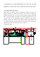
Electrical wiring diagram 3 phases Single phase 7
SIGN NAME TYPE M Motor 3 phase Y90L-4 Single phase KM YC100L-4 AC magnetic contactor LC1-D129 (3 phase0 LC1-D259(single phase) KA1 Relay CA2-DN22 TC Transformer JBK3-63 SA1 Power switch HZ5B-10/2D009 SB1 Emergency stop button LA25-01ZS SB2 Job button LA25-10 HL Power indicator light AD11-30/20 5.LUBRICATION SYSTEM (A) Head stock Ensure that the head stock is filled to the level of the relevant oil sight glass with Tellus 32 of Shell oil.
Fill the oil by taking off the inlet cap, which is fitted at the top on the right hand side of the apron . (D) Change gears Lubricate the change gears with thick machine oil or grease once a month . (E) Other portions There are oil inlets on input shaft bracket of gearboxs , handwheel bracket of apron , feed rod bracket of carriage , saddle , cross slide , toolpost, thread dial indicator , tailstock and the bracket which holds the leadscrew & feed rod . handing oil is required from time to time .
Lubrication table No.
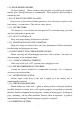
Operation diagram 1.Forward/reverse switch 4.Four steps speed selector 2.Handle 3.Feed direction selector 5.Low/high speed selector 6.Knob component 7.Steady rest 8.Longitudinal traverse hand wheel 9.cross traverse hand wheel 10.Follow rest 11.Toolpost handle 12.Toolpost traverse handle 13.Tailstock quill clamping lever 14.Tailstock quill traverse hand wheel 15.Tailstock set-over screw 16.Thread dial indicator 17.Controlling lever 18.Machine stand 19.Thread cutting engagement lever 20.
6.1SPINDLE SPEED CONTROL (refer to operation diagram) A. Identification before operation (1) Ensure that lubrication has been carried out in accordance with the lubrication charts. (2) When rotating the spindle, it is mechanized to the gear box and apron. Check that the forward / reverse switch (No. 1) or the knob component(No.6)( when it is mounted by option ) is in the Stop position ; the feed axis selector (No.20) and the thread cutting engagement lever (No.19) are in diseneaged position .
6.2 SPINDLE NOSE (CAM LOCK D1-4”) MOUNTING OF CHUCKS, FACEPLATES AND OTHER SPINDLE MOUNTED ATTACHMENTS Ensure that the location faces on both nose and attachment are scrupulously cleaned. Check that all the cams are in the release position (fig . 1) Mount the attachment on to the spindle nose and lock each cam by turning it clockwise using the key provided. A reference line R1 (fig .1) should be scribed on each chuck or faceplate to coincide with the reference line R on the spindle nose.
handle (No.12) The carriage is anchored by turning the carriage lock in clockwise direction. (B) Replacement of change gears. Open the end cover firstly, Then loose both the hexagon nut of the clamping bolt and the clamping screw of the swing frame to exchange the transmission shaft gear with another gear. And the change of driven gear is made by loosening the 120T and 127T gear shaft clamping nut . it is necessary for suitable backlash to intermediate the gears in both cases .
b. Longitudinal and cross feed table in metric lead screw. (2) Thread table a. Thread table for imperial lead screw.
b. Thread table for metric lead screw.
(E)Threading dial indicator Threading dial indicator (No.16) is installed on the right hand side of apron. The indicator is used for thread cutting to engage with lead screw . To cut threads on the chart, close the lead screw nut at the appointed line of the dial according to the indicator chart, Ensure the appropriate dial line coincide exactly with fixed point each pass .
gear of mesh with the lead screw tightly when out in use. a. IMPERIAL THREADS ON IMPERIAL LEADSCREW MACHINES OR METRIC THREADS ON METEIC LEADSCREW MACHINES For these threads it is recommended that the thread dial indicator be used this allows the half nut of lead screw to be engaged at the end of each thread cutting pass, provided that are reengaged in accordance with the indicator table mounted on the left hand side of the apron . b.
C D E F (B) Saddle strip Wear on the rear saddle gib strip (A) may be accommodated by adjustment of the socket head set screws . A The procedure for adjustment is to first release the hexagon nuts (B) B and turn the socket head set screws(C) slightly in clockwise and then reclamp the hexagon nuts, Care should be taken to avoid over adjustment 45 C 0 turn at the socket head set screw approximately 0.125mm (0.05") taken up in the gib.
the end edge of the feed rod . Turn the socket head cap screw in a clockwise direction as require. Care should be taken to avoid over adjustment ; every 45 0 turn at the socket head cap screw represents approximately 0.125mm (0.05") taken up of back lash . (F) Cross slide and toolpost Toolpost is carried on a rotatable swivel table fitted as standard onto the cross slide, and the top of cross slide is graduated both - 45 0 ~ 0 and 0 ~ 45 0 for accurate indexing of swivel table.
lubrication plan sheet) to keep the machine properly lubricated. 3) Check all the running parts not too tight, or loose. Bearing of headstock, longitudinal and cross feed, tool holders etc would be exmined and adjusted by hand or proper fitness. 4) Check the sensitivity & reliability of all manual control levers: To try the speed change rate function of headstock feeds and apron in gear box and inspect their starting, stopping and forward & reverse action whether they are sensitive and reliable or not.
To feel the temperature of motor bearing at the case of full load. 3) Noise and vibration: If you find the noise and vibration of the machine are abnormal or irregular. Stop the machine immediately for inspection and adjustment. 4) Quality of products: If you discover the quality of products is out of limit, stop the machine at once for finding the causes of defects. 5) Safety affairs: a. Must stop operation when you leave the machine. b. When changing main spindle speed or feeding speed stop running first.
2) Electrical system: Carefully examine the connection of all electrical wires, terminals and switches, which occasionally have been damaged by chips or others. 8.4.3SEMI-YEARLY INSPECTION: 1) Change oil in gear box: Remove the used oil from gear box of headstock, feed and replenish with fresh oil. 2) Check the wear and tear of all gears in gears and packing: Inspect the damage of all gears in various box. Spindle and bearings, and packing. Repair or replace it if necessary.
9.TROUBLE SHOOTING TROUBLE PROBABLE CAUSES Overheat headstock bearing REMEDY of 1.Oil level in headstock is Check the oil level and too low or too high. replenish or discharge the oil to the proper level. 2.Quality and viscosity of oil Replace the oil with is wrong. recommended one. 3.Oil is too dirty Replace oil. 4.Oil hole in bearing Remove the dirt from obstructed by dirt. the oil hole. 5.Bearing obstructed by dirt Clean the bearing and renew it. 6.Badly worn bearing. Replace bearing. 7.
Chatter 18.Clamp of workpiece in from loose status. 19.Spindle bearing thrust too loose. 20.Headstock is not tight with bedway. 21.Excess clearance between carriage 22.Excess clearance in cross or compound slide. 23.Cutting angle of cutting tool is not correct. 24.Edge of cutting tool has been worn-out. 25.Weak of tool shank and too long for extension. 26.Tool fixed to holder not tight enough. 27.Unbalances of workpiece or chuck when high speed revolution. 28.
Misalliance of 33.Incorrect position of cam. chuck with main spindle. Uneasy to cut the 34.Excessive clearance of thread lead screw in axial direction. 35.Excessive clearance between saddle or cross slide or cross slide and tool post slide. 36.Worn thread or nut in cross slide or tool post slide. 37.Excessive clearance of handwheel. Tailstock is 38.Clamp handle lever too uneasy to clamp long or too short. with bed stably. 26 Adjust cam and lock in proper position.
27
Bed Assembly Index No. 1 2 3 4 5 6 7 8 9 10 11 12 13 14 15 16 17 18 19 20 21 22 23 24 25 26 27 28 29 30 31 32 33 34 35 36 37 38 39 40 41 42 43 44 Part No. GB/T70 GB/T41 GB/T881 CZ1340G-01-015 GB/T77 CZ1340G-07-028 GB/T5780 CZ1340G-01-016 GB/T117 GB/T70 CZ1340G-01-017 CZ1340G-07-058 CZ1340G-01-024 CZ1340G-01-024 CZ1340G-01-024 GB/T70 GB/T117 GB/T1155 GB/T70 GB/T119 CZ1340G-01-025 CZ1340G-01-030 CZ1340G-01-028 CZ1340G-01-029 GB/T2089 CZ1340G-07-057 GB/T6172 GB/T79 GB/T879 CZ1340G-01-026 JB/T7271.
Index No. 45 46 47 48 49 Part No.
Headstock Assembly Index No. Part No. Description Size 1 2 3 4 5 6 7 8 9 10 11 12 13 14 15 16 17 18 19 20 21 22 23 24 25 26 27 28 29 30 31 32 33 34 35 36 37 38 39 40 41 42 43 44 GB/T70 CZ1340G-02-009 CZ1340G-02T01-001 CZ1340G-02-008 GB/T77 CZ1340G-02-031 GB/T7757.2 GB/T276 CZ1340G-02-030 GB/T1096 CZ1340G-02-032 CZ1340G-02-029 CZ1340G-02-028 CZ1340G-02-027 CZ1340G-02-067 CZ1340G-02-065 CZ1340G-02-066 CZ1340G-02-064 CZ1340G-02-063 GB/T70 CZ1340G-02-026 GB/T7757.
Index No. Part No. Description Size 45 46 47 48 49 50 51 52 53 54 55 56 57 58 59 60 61 62 63 64 65 66 67 68 69 70 71 72 73 74 75 76 77 78 79 80 81 82 83 84 85 86 87 88 89 GB/T70 CZ1340G-02-011 CZ1340G-02-012 GB/T279 Gb/T894.1 CZ1340G-02-036 CZ1340G-02-033 GB/T1096 CZ1340G-02-037 GB/T894.1 GB/T297 CZ1340G-02-062 CZ1340G-02-005 CZ1340G-02-004 GB/T70 CZ1340G-02-002 GB/T810 CZ1340G-02-001 CZ1340G-02-003 GB/T1096 GB/T1096 CZ1340G-02-034 CZ1340G-02-035 GB/T2089 GB/T70 JB/T7941.1 GB/T70 GB/T97.
Index No. Part No. Description 90 91 92 93 94 95 96 97 98 99 100 101 102 103 GB/T879 GB/T1096 GB/T7757.2 CZ1340G-02-056 GB/T10708.3 CZ1340G-02-057 GB/T97.1 GB/T41 CZ1340G-02-024 GB/T7757.2 CZ1340G-02-020 GB/T879 CZ1340G-02-023 CZ1340G-02-040 Pin Key O-Ring Washer Oil Seal Gear Washer Nut Shift Lever O-Ring Shift Fort Pin Shaft Gear 33 Size 3×10 ×18 13.8×3.1 24×32×5 40T 12 M12 11.8×1.8 5×32 51T Qty.
31
Inlaid Block Assembly Index No. Part No. Description 1 2 3 4 5 6 7 8 9 10 11 12 13 14 15 16 17 18 19 20 21 22 23 24 25 26 27 28 29 30 31 32 33 34 35 36 37 38 39 CZ1340G-02-046 GB/T308 GB/T2089 GB/T77 GB/T71 CZ1340G-02-068 JB/T7271.5 CZ1340G-02-044 CZ1340G-02-043 GB/T308 GB/T2089 GB/T77 CZ1340G-02-058 GB/T77 GB/T2089 CZ1340G-02-060 GB/T70 CZ1340G-02-042 GB/T894.1 GB/T818 CZ1340G-02T01-006 CZ1340G-02T01-005 GB/T7757.2 GB/T1096 CZ1340G-02T01-002 GB/T7757.
32
Gearbox Assembly Index No. 3 4 5 Part No.
Gearbox Assembly Index No. 48 49 50 51 47 48 49 50 51 52 53 54 55 56 57 58 59 60 61 62 63 64 65 66 67 68 69 70 71 72 73 74 75 76 77 78 79 80 81 82 83 84 85 86 87 88 89 Part No. CZ1340G-07-003 GB/T70 GB/T3452.1 D97-4-20 CZ1340G-07-002 CZ1340G-07-003 GB/T70 GB/T3452.1 D97-4-20 GB/T70 GB/T117 GB/T9877.
Index No. 90 91 92 93 94 95 96 Part No. GB/T879 GB/T1160.1 CZ1340G-07-036 GB/T308 GB/T2089 GB/T77 CZ1340G-07-041 Description Pin Oil Sight Glass Handle Body Steel Ball Spring Screw Panel 35 Size 4×25 20 6.5 1×5×20 M8×10 Qty.
36
Apron Assembly Index NO. Part NO. Description Size Qty 1 2 3 4 5 6 GB/T5780 CZ1340G-04-030 CZ1340G-04-016 GB/T1096 CZ1340G-04-015 GB/T3452.1 Screw Washer Gear Key Shaft O-Ring M6*10 1 1 1 1 1 1 7 8 9 10 11 12 13 14 15 16 17 18 19 20 21 22 23 24 25 26 27 28 29 30 31 32 33 34 35 36 37 38 39 40 41 42 43 44 45 46 CZ1340G-04-013 GB/T879 CZ1340G-04-004 GB/T879 CZ1340G-04-005 CZ1340G-04-047 GB/T70 CZ1340G-04-001 GB/T3452.1 GB/T5781 CZ1340G-04-029 CZ1340G-04-002 GB/T1096 JB/T7940.
Index NO. Part NO. Description Size Qty 47 48 49 50 51 52 53 54 55 56 57 58 59 60 61 62 63 64 65 66 67 68 69 70 71 72 73 74 75 76 77 78 79 80 81 82 83 84 GB/T77 CZ1340G-04-023 JB/T7941.1 CZ1340G-04-041 CZ1340G-04-033 CZ1340G-04-026 GB/T70 CZ1340G-04-012 CZ1340G-04-011 CZ1340G-04-010 GB/T70 GB/T83 GB/T77 CZ1340G-04-034 CZ1340G-04-018 GB/T5781 GB/T79 GB/T6170 GB/T5781 CZ1340G-04-019 GB/T6170 GB/T77 CZ1340G-04-021 GB/T119 CZ1340G-04-017 CZ1340G-04-020 CZ1340G-04-042 GB/T4141.
39
Saddle and Cross Slide Assembly Index NO Part NO Description 1 2 3 4 5 6 7 8 9 10 11 12 13 14 15 16 17 18 19 20 21 22 23 24 25 26 27 28 29 30 31 32 33 34 35 36 37 38 39 40 41 42 43 44 45 46 47 48 49 50 JB/T4141.5 CZ1340G-05-023 CZ1340G-05-022 CZ1340G-05-021 CZ1340G-05-038 GB/T77 GB/T70 GB/T301 CZ1340G-05-020 JB/T7940.4 GB/T5781 CZ1340G-05-013 CZ1340G-05-039 GB/T823 CZ1340G-05-013 CZ1340G-05-014 GB/T70 GB/T118 CZ1340G-05-006 CZ1340G-05-007 GB/T6170 GB/T71 GB/T5781 JB/T7940.
41
Tool Post Assembly Index NO Part NO Description Size QTY 1 2 3 4 5 6 7 8 9 10 11 12 13 14 15 16 17 18 19 20 21 22 23 24 25 26 27 28 29 JB/T7271.5 JB/T7271.6 CZ1340G-05-026 CZ1340G-05-024 GB/T83 CZ1340G-05-029 CZ1340G-05-025 GB/T78 CZ1340G-05-030 GB/T2089 CZ1340G-05-028 JB/T7940.4 GB/T78-85 GB/T301 CZ1340G-05-034 GB/T70 GB/T6173 GB/T78 CZ1340G-05-036 GB/T117 GB/T72701.9 CZ1340G-05-035 CZ1340G-05-033 GB/T6170 GB/T97.
43
Tailstock assembly Index No. Part No. Description 1 2 3 4 5 6 7 8 9 10 11 CZ1340G-06-020 CZ1340G-06-017 CZ1340G-06-018 GB/T879 GB/T41 GB/T79 CZ1340G-06-019 JB/T7271.5 CZ1340G-06-012 JB/T7271.5 CZ1340G-06-013 Base Screw Collar Pin Nut Screw Shaft Knob Lever Knob Screw 12 CZ1340G-06-015 Shaft 1 13 14 15 16 17 18 19 20 21 22 23 24 25 26 27 28 29 30 31 32 33 34 35 36 37 CZ1340G-06-014 JB/T7940.
45
Electric Box Assembly Index No. Part No. Description 1 2 3 4 5 6 7 8 9 10 11 12 13 14 15 16 17 18 19 20 21 22 23 24 CZ1340G-09-001 CZ1340G-09-007 CZ1340G-09-005 CZ1340G-09-011(1) XB7-EA.1 XB2-ES542 XB7-EV6 GB/T818 LC1-D259 GB/T818 CZ1340G-09-006 GB/T41 GB/T818 JH9-1.
47
Follow Rest Index No. 1 2 3 4 5 6 7 8 9 10 11 Part No. JB/T7274.
49
Steady Rest Index No. 1 2 3 4 5 6 7 8 9 10 11 12 13 14 15 16 17 18 19 Part No. JB/T7274.