
User manual

EK6020CB_IM 02.08.18
20
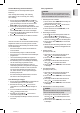
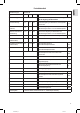
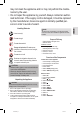
Display
20 Selection position (
)
21 Weekday
22 Timer active ( )
23 Standby ( )
24 Temperature in °C or timer setting number
25 Timer turn-off time (OFF)
26 Timer start time (ON)
27 Time ( )
28 Automatic, adaptive start control function of the heater
(AUTO)
29 Intensity of the flames ( )
30 Heating power of 900 W ( ) or 1800 W ( )
Assembly Instructions
This appliance is intended for permanent attachment to a
wall. It should be placed at least 30 cm above the ground.
Please refer to the gures on page 4.
Do not switch on the appliance until it has been prop-
erly installed!
WARNING:
Make sure beforehand whether there are cables inside
the wall which could be damaged!
CAUTION:
• The wall should be a load bearing and heat resistant
wall.
• Do not hold the appliance using the glass front.
• The subsequent work requires manual skills. If neces-
sary, get help from a specialist
NOTE:
• There must be a power outlet nearby, but not above
the appliance. The hot air ow is emitted by the fan at
the top of the appliance.
• Route the power cord right behind the appliance.
• In order to have an optimal view at the replace, we
recommend installing it onto a height of 60 cm (see
Fig. A).
• Use a size 8 drill bit to drill holes into the wall.
• You will also need a medium sized Phillips screwdriver.
1. Gently place the appliance on the oor leaning against
a wall.
2. Use both hands to pull out the glass front evenly up-
wards. Set the glass front aside.
3. Measure the height at which you want to mount the
appliance. The recommended dimensions can be found
in Fig. B.
4. Use 4 screws and dowels to attach the mounting strip
horizontally to the wall.
5. Attach the mounting bracket with the threaded screws to
the appliance.
6. Hang the appliance into the mounting strip on the wall.
7. Mark the positions of the 2 boreholes for the mounting
bracket.
8. Remove the appliance from the wall once again.
9. Drill the 2 holes for the mounting bracket. Insert the
dowels.
10. Hang the appliance into the mounting strip on the wall.
11. Use 2 screws to attach the mounting bracket to the wall.
12. Hang the glass front back into the appliance. To do this,
see Fig. D.
Electrical Connection
Power Requirements
The appliance can consume a total of 1800 W. With this
connected load a separate supply line protected by a 16 A
household circuit breaker is recommended.
CAUTION: Overload!
• If you use extension leads, these should have a cable
cross-section of at least 1.5 mm².
• Do not use any multiple sockets, as this appliance is
too powerful.
• Do not connect any other powerful appliances to the
same electric circuit.
Connection
• Make sure that the iron voltage and the line voltage
match. The nameplate is located at the bottom of the
appliance.
• The mains plug should only be inserted into a correctly
installed socket with earthing contact.
Remote Control
Inserting the Batteries (Batteries not included)
1. Open the battery compartment cover on the back of the
remote control.
2. Insert 2 batteries of type “AAA” • 1.5 V • MICRO, ob-
serving the correct polarity (see markings on the bottom
of the compartment)!
3. Close the battery compartment cover.
Remote Control Range
• The remote control has a range of approx. 10 meters. If
the range decreases you should change the batteries.
• Make sure there are no obstacles between the remote
control and the sensor of the appliance. It is located in
the upper left area of the glass front.