
Operator`s manual

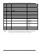


Operating Instructions FR 125 MAX, FR 125 Junior MAX and FR 125 Mini MAX
Seite/page 60/104
Ausgabe/edition 02/2006
Warning: Pay attention to instructions of the chassis manufacturer regarding the drive chain
alignment.
Establish required chain tension (Sag = +/- 5 mm / +/- 0,20 in) by shifting of the
engine.
Fasten engine on the chassis
Warning: Take note of advice of the chassis manufacturer regarding engine suspension on
chassis.
¡ Note: If you find in the equipment carton a synthetic strap with the dimensions 800 x 65
mm it may be used to cover the drive chain. This cover can be attached via the
holes provided on the lower coolant hose with a cable tie. The cover should be
routed in a curved path from the lower coolant hose to the chain guard fixtures
provided on the chassis. The necessary holes for securing the cover on the two
supports have to be made according to the position on the chassis.
Warning: This cover serves merely as splash protection against the grease on the drive chain,
but is no protection against contact with the moving parts of the centrifugal clutch
and the drive train!
Warning: During kart operation beware of any contact of body or clothing with moving parts of
the kart (drive chain, rear axle and wheels). Risk of injury.
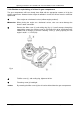
6. Fitting of the start button and of ON/OFF switch
Both items have to be fitted either right or left into top section of the front shield where the best
possible protection against dampness is provided.
Drill 22 mm dia. / 1/8 “ hole for the starter button (2)
into either left or right side of front shield.
Approx. 40 mm / 1 ½ “below drill a 12 mm dia. / ½ “
hole for the ON/OFF switch (1).
Attach start button furnished with rubber cap by hex.
nut on front shield.
Fig. 4
Attach ON/OFF switch on the front shield with the 2 nuts supplied.
¡ Note: Hand-tighten the attachment nut of starter button and ON/OFF switch.