* 1980 OPERATOR'S MANUAL l.
model V.I.N. purchase date _ warranty expiry date DEALER IMPRINT AREA TECHNICAL INFORMATION CENTRE AFTER SALES SERVICE DEPARTMENT BOMBARDIER LIMITED VALCOURT, QUEBEC CANADA, JOE2LO The following are trademarks of Bombardier Limited.
INDEX FOREWORD SAFETY IN MAINTENANCE 2 3 CONTROLS/INSTRUMENTS Throttle lever, brake lever, ignition light switch, headlamp dimmer switch, emergency cut-out switch, light switch, manual starter handle, primer, tether cut-out switch, adjustable steering, speedometer (optional on some models), hood opening, tool box, fuel gauge 4 BREAK-IN PERIOD Break-in, inspection, inspection checklist 8 FUEL MIXING Recommended gasoline, recommended oil, fuel mixture ratio, fuel mixing procedure, injection oil 8 PRE-STAR
FOREWORD CONGRATULATIONS ... You are now the proud owner of a new 1980 Bombardier snowmobile. This vehicle is the result of incomparable teamwork between Bombardier designers, engineers and technicians. Consequently, this vehicle is designed and engineered with safety, handling, comfort and quietness in mind.
SAFETY IN MAINTENANCE Observe the following precautions: • Throttle mechanism should be checked for free movement before starting engine. • Engine should be running only when pulley guard is secured in place. • Never run the engine without drive belt installed. Running an unloaded engine can prove to be dangerous. • Never run the engine when the track is raised off the ground. • It can be dangerous to run engine with the cab removed. • Gasoline is flammable and explosive under certain conditions.
CONTROLS/INSTRUMENTS B A 1~~f1'::.:;;:J\-;;iiiiiiii~'\'·L~~ H ~~--G AJ Throttle Control Lever BJ Brake Control Lever CJ Ignition/Light Switch DJ Headlamp Dimmer Switch EJ Emergency Cut-Out Switch F) Light Switch (Electric Model) G) Manual Starter Handle H) Primer I) Tether Cut-Out Switch J) Adjustable Steering Handle KJ Speedometer (Optional on Some Models) A) Throttle Control Lever Located on right side of handlebar.
D) Headlamp Dimmer Switch I) Tether Cut-Out Switch The dimmer switch, located on left side of handlebar, allows correct selection of headlamp beam. To obtain high or low beam simply depress switch. Attach tether cord to wrist or other convenient location then snap tether cut-out cap over receptacle before starting engine. E) Emergency Cut-Out Switch If emergency engine "shut off" is required, completely pull cap from safety switch and engine power will be automatically shut 1I 0 ff " .
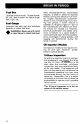
BREAK..IN PERIOD Tool Box Located under the cab. To gain access, tilt cab. Ideal location for spare plugs, belt, rope, etc. Fuel Gauge Unscrew fuel tank cap and withdraw dipstick to check fuel level. .... WARNING: Never use a lit match .... or open-flame to check fuel level. With Bombardier-Rotax snowmobile engines, a break-in period is required before running the vehicle at full throttle. Engine manufacturer recommendation is10to 15 operating hours. During this period, a richer mixture is needed (i.e.
1G-HOUR INSPECTION CHECK LIST Engine timing I Fan belt tension Spark plug(s} condition: (Remove and clean) Carburetor adjustment Oil injection pump adjustment .
FUEL MIXING On models not equipped with oil injection, oil must be added to the gasoline in pre-measured amounts then both oil and gasoline should be throughly mixed together before fueling the tank. Recommended Gasoline Use regular leaded gasoline available from all service stations. . . . CAUTION: Never experiment • with different fuel or fuel ratios. Never use naphtha, methanol or similar products, Recommended Oil Use concentrated Bombardier snowmobile oil available from your dealer.
3. Replace container cap and shake the container thoroughly. Check level and refill every time you refuel. 4. Add the remainder of the gasoline. 5. Once again thoroughly agitate the container. Then using a funnel with a fine mesh screen to prevent the entry of water and foreign particles, transfer mixture from container into the snowmobile tank. NOTE: When using pre-mixed fuel, always shake the container thoroughly as the oil has a tendency to settle.
PRE-START CHECK Check Points STARTING PROCEDURE Emergency Cut-Out Button • Activate the throttle control lever several times to check that it operates easily and smoothly. The throttle control lever must return to idle position when released. • Check fuel level. • Check injection oil level (if applicable). • Check that the skis and the track are not frozen to the ground or snow surface and that steering operates freely.
Electric Starting Emergency Starting . . . CAUTION: Never operate your . . snowmobile with the battery removed or disconnected. 1. Insert key in ignition switch. 2. Test throttle control lever. Activate primer (2 or 3 times). NOTE: Primer is not necessary when engine is warm. 3. Make sure that the tether cut-out cap is in position and that the cord is attached to your clothing. Check that the emergency cut-out button is in the released upper position.
lUBRICATION Dual Carburetor Models (with roller square shaft pulley) Remove the pulley guard from the vehicle and wind the emergency rope tight around the drive pulley between the sliding half and the roller guard. Start the engine as per usual manual starting. ..... WARNING: When starting the .... vehicle in an emergency situation by the drive pulley, do not make a knot at the end of the emergency rope and do not reinstall the pulley guard.
Pulley Guard Removal .... WARNING: Pulley guard shouu, .... always be in place when engine is running. 3. Open the driven pulley by twisting and pushing the sliding half. Hold in fully open position . A. Raise the hood and pull up the front retaining pin; pry the guard removal rearward and raise the guard. B. Pull the guard out of the center retaining bolt. C. Remove the retaining clip of the rear pin and remove the pin. D. Remove the guard. 4. Slip the belt over the top edge of the sliding half. 5.
Slip the belt out from the drive pulley. Steering Mechanism WARNING: Do not lubricate throttle and/or brake cables and • housings. Lubricate the ski legs at grease fittings until new grease appears at joints. Oil spring coupler bolts . WARNING: It may necessary to loosen the brake adjustment in • order to easily lift the countershaft. Always check that the brake disc is correctly installed between the brake pads and that the brake is well adjusted. Check brake light operation.
MAINTENANCE The following Maintenance Chart indcates regular servicing schedulesto be performed by you or your servicing dealer. If these services are performed as suggested, your snowmobile will give you many years of low-cost use. .&. WARNING: Only perform such . . . procedures as detailed in this manual. It is recommended that dealer assistance be periodically obtain~ on other components/systems not coered in this manual.
• A light grey insulator tip indicates a lean mixture caused by; carburetor high speed mixture adjusted too lean, wrong spark plug heat range, incorrect fuel mixture ratio, or a leaking seal or gasket. Overheated (light grey) Fouled (black) CAUTION: If spark plug condi• tion is not ideal, contact your authorized dealer. Check spark plug gap using a wire feeler gauge. Reinstall plugs and connect wires. (W2) Battery (Electric Start Models) Check electrolyte level.
(WS) Track Tension and Alignment The suspension is adjustable, the front adjustment for surface condition, the rear for driver's weight. When the front adjuster blocks are at the lowest elevation more weight is distributed on the skis. At the highest position the weight is transferred to the track. The rear adjuster blocks should be adjusted to suit the driver's preference. ~ CAUTION: Too much tension will result in power loss and excessive stresses on suspension components. If necessary to adjust.
To correct, stop the engine, loosen the rear idler wheels retaining screws then loosen the lock nuts and tighten the adjuster bolt on side where the slider shoe is the furthest to the track insert guides. Tighten lock nuts and recheck the alignment. Ensure to retighten the idler wheel retaining screws. BI Throttle Slide Adjustment WARNING: Ensure the engine is • turned OFF I prior to the throttle slide adjustment.
CW7) Drive Belt Inspect the belt for cracks, fraying or abnormal wear (uneven wear, wear on one side, etc.) If abnormal wear is noted, probable cause is pulley misalignment. Contact your dealer. Check the drive belt width, if less than 3 em (1 3/16") replace. O NOTE: When installing a new drive belt, a break-in period of 1525 km (10-15 miles) is strongly recommended.
. . . WARNING: Whenever the brake ~ is readjusted, the brake light switch operation mustalso be checked and adjusted as needed. 1M2) Steering Adjustment Skis should have a toe out of 3 mm (1/8"). To check, measure the distance between each ski at the front and rear of the leaf springs. The front distance should be 3 mm (1/8") more than the rear when the handlebar is horizontal. IMPORTANT: Closethe front of the skis manually to eliminate all slack from the steering mechanism.
if belt seems damaged or if tension is incorrect, contact your dealer immediately. ,.&. WARNING: If fan protector is removed, always reinstall after servicing. T (M7) General Inspection Check the electrical wiring and components, retighten loose connections. Check for stripped wires or damaged insulation. Thoroughly inspect the vehicle and tighten loose bolts, nuts and linkage. Inspect skis and ski runners for wear.
STORAGE Bulb Replacement If the headlamp bulb is burnt, tilt cab, unplug the connector from the headlamp. Remove the rubber boot and unfasten bulb retainer clips. Detach the bulb and replace. If taillight bulb is burnt, expose the bulb by removing the red plastic lens. To remove, unscrew the two (2) Phillips head screws. Verify all lights after replacement. It is during summer, or when ~ vehicle is not in use for any length of time that proper storage is a necessity.
Ski Wash or brush all dirt or rust accumulation from the skis and springs. Grease the ski legs at the grease fittings. Check the condition of the skis, IMPORTANT: The drive pulley assembly will be excluded from warranty, if the factory seal is broken by other than a duly authorized representative of Bombardier. ski runners and leaf springs. Replace if worn or weak. Fuel Tank Remove the cap then using a syphon, remove the gasoline from tank .
Remove the spark plugs. Operate the rewind starter to bring the piston at top position. Pour the equivalent of one spoonful of oil into spark plug hole. Slowly crank the engine several times using the manual starter. Repeat above steps for other cylinder. Install the spark plugs. _ CAUTION: To prevent ignition ..". system damage, make sure that the cut-out button is in the lower position. Battery Remove battery from vehicle and clean outside surface of battery with solution of baking soda and water.
. . , CAUTION: If for some reason the ... snowmobile has to be stored outside it is necessary to cover it with an opaque tarpaulin. This caution will prevent the sun rays affecting the plastic components and the vehicle finish. General Inspection Check the electrical wiring and components, retighten loose connections. Check for stripped wires or damaged insulation. Thoroughly inspect the vehicle and tighten loose bolts, nuts and linkage.
PRE-SEASON PREPARATION Snow is falling and you are now anticipating the next snowmobile safari. If you have observed and adhered to the storage procedures outlined in this manual, your vehicle preparation becomes a relatively easy task. To simplify the pre-season preparation we have drawn up a small chart. The chart indicates servicing points to be performed by you and your servicing dealer. If these services are performed as suggested, your vehicle will give you many hours of fun and low cost use.
TROUBLE SHOOTING SYMPTOMS POSSIBLE CAUSES WHAT TO DO Engine turns over but fails to start or starts with difficulty 1. No fuel to the engine Check the tank level and fill up with correct gas-oil mixture. Check for possible clogging of fuel line, item 5. 2. Flooded engine Remove wetspark plugs, turn ignition to OFF and crank engine several times. Install clean dry spark plugs. Stan engine following usual staning procedure. If engine continues to flood, see your dealer. 3.
SYMPTOMS POSSIBLE CAUSES WHAT TO DO Engine lacks acceleration or power 1. Fouled or defective spark plug Check item 3 of "Engine turns over but fails to start or starts with difficulty" 2. Clogged fuel line (water or Check fuel line condition. ISee item 4 of "Engine turns over but fails to start or starts with difficulty"!' dirt) 3. Carburetors 4. Faulty ignition Readjust the carburetor. ISee Maintenance section!. If trouble persists, contact your dealer.
TOOLS As standard equipment each new snowmobile is supplied with a basic tool kit such as screwdriver, wrenches, emergency starter rope, etc ... Standard Tools A ~===~-"""-'g c ~G E o A. Screwdriver B. Socket 21/26 mm C. Socket 10/13 mm D. Socket handle E. Angular wrench 10/13 mm F. Starter rope G.
SPECIFICATIONS ENGINE No. of cylinders Bore Stroke Displacement Compression ratio (corrected) Carburetor type Carburetor adjustment: - air screw - idle speed Engine head nuts (torque) CHASSIS Overall length Overall width Overall height Ski stance (center to center) Ski alignment (toe out) Weight Bearing area Ground pressure CITATION 3500 CITATION 4500 CITATIONSS 1 72 mm (2.83") 66 mm (2.60") 268.7 cm 3 (16.4 in3) 6.7:1 2 62 mm (2.44") 61 mm (2.40") 368.3 cm 3 (22.47 in3) 6.9:1 2 62 mm (2.
I CITATION 3500 BRAKE Brake type Brake adjustment (control lever) Brake lining (minimum thickness) I CITATION 4500 I CITATION SS Disc, adjust as required. 13 mm (112") minimum distance from handlebar grip when fully applied.
W tv OFF ON IGNITION SWITCH TETHER CUT-OUT SWITCH VI/WH VI/WH VI VI BK GY/VI GY SINGLE CYLINDER MODEL YL BK CD CD @ o ® ® Q) LIGHTING COIL 110 W LIGHTING COIL 30 W IGNITION COIL HEADLAMP (45/45 WI LAMP 15 WI TAILLAMP (5-21 WI FUSE 1.
RD --!!.e. ROIGN IGNITION C;WITCH KILL SWITCH 'I'll GY GV ~ DIMMER SWITCH RO/Vl BI( OPTIONAL SPEEDOMETER GN GN RO GN aVIVl GV ELECTRIC STARTMODEL ~ @ ® ® G) ® i @ @ w w LIGHTING COIL 110 W LiGHTING COIL 30 W IGNITION GENERATOR COIL Fuse 130 A.I FUSE (.1 AI FUSE 115A.) HEADLAMP G) BI': HEAD LAMP 145145 WI TAILLAMP 15-21 WI LIGHT 15WI BATTERY 124A.I STARTER SOLENOiD SWITCH REGULATOR RECTIFIER "Brown on some models ,'--):-0...
W .f:!o VI/WH VI/WH VI VI VOLTAGE REGULATOR BK GY/Vl GY Yl BK BK TWIN CYLINDER MANUALSTART MODEL COIL 110 W COIL 30 W IGNITION COIL SPEEDOMETER OPTIONAL ON SOME MODELS '"
5.1.* METRIC INFORMATION GUIDE BASE UNITS SYMBOL DESCRIPTION UNIT length mass liquid temperature pressure torque speed meter kilogram liter celsius kilopascal Newton meter kilometer per hour m kg L °C kPa N.m km/h PREFIXES PREFIX kilo centi milli SYMBOL MEANING VALUE k one thousand one hundredth of a one thousandth of a 1,000 c m 0.01 0'.001 *THE INTERNATIONAL SYSTEM OF UNITS (SYSTEME INTERNATIONAL) ABREVIATES "SI" IN ALL LANGUAGES.
LIMITED WARRANTY SKI-DOOR SNOWMOBILES 1980 BOMBARDIER Limited as manufacturer, warrants FROM THE DATE OF FIRST CONSUMER SALE, every 1980 Ski-Doo® snowmobile, sold as NEW AND UNUSED, by an authorized SKI-DOO dealer, subject to the following limitations and conditions, for a period of: • two (2) seasons maximum for models: Elan® , Citation*, Everest® , Elite® , Warranty STARTS on the date of sale to the first consumer and I:NDS the SECOND APRIL 30TH following the date warranty coverage started.
EXCLUSIONS Items and components: Any of the following expendable items and/or components that are damaged or worn due to normal use: variable speed drive belt, windshield, filters, ignition breaker points, condensers, spark plugs, light bulbs, protective lenses, brake linings, ski runner shoes, slider shoes on suspension and variable speed pulleys, labels, soft trim, appearance items, lubricants and paints and all tune-ups, seized, melted or holed piston and adjustments required.
Some states or provinces do not allow the exclusion or limitation of incidental or consequential damages, so the above limitation or exclusion may not apply. CONDITION TO HAVE WARRANTY WORK PERFORMED Present, to the servicing dealer, the hard copy of the BOMBARDIER Customer Registration card given by the selling dealer at time of purchase.
Bombardier Limited reserves the right to modify its warranty policy at any time, being understood that such modification will not alter the warranty conditions applicable to vehicles sold while the-above warranty is in effect.
OFTEN ASKED QUESTIONS Q: Why must my snowmobile be registered? After all I do have my original invoice as proof of when I purchased my snowmobile. A: The information provided by the Customer Warranty Registration card is computerized, and al/ warranty claims thereafter, are processed by the computer. Without this valuable information on the Warranty Registration Card, we cannot acknowledge warranty or notify owners of a possible safety recall.
0: What costs are my responsibility during the warranty period? A: The customer's responsibility includes all costs of normal maintenance services, non-warranty repairs, accidents- and collision damage, as well as oils, and spark plugs, and incidental or consequential damages costs as explained in the warranty. . 0: Are "Genuine" Bombardier replacement parts used in warranty repairs covered by warranty? A: Yes.
HOW TO IDENTIFY YOUR SNOWMOBILE The main components of your snowmobile (engine, track and frame) are identified by different serial numbers. It may sometimes become necessary to locate these numbers for warranty purposes or to trace your snowmobile in the event of theft. ENGINE SERIAL NUMBER TRACK SERIAL NUMBER 911"O£>\lZ~ L:l""'--VEHICLE SERIAL NUMBER/' , '---..", O 42 NOTE: We strongly recommend that you take note of all the serial numbers on your vehicle and supply them to your insurance company.
CHANGE OF ADDRESS AND OWNERSHIP Any change in address or ownership should be brought to the attention of the manufacturer by completing and sending out the card supplied below. This will help us to maintain our files up-to-date. ~ : : CHANGE OF ADDRESS : VEHICLE IDENTIFICATION NUMBER : OLD ADDRESS: NAME NO CITY STREET APT. ZIP / POSTAL CODE STATE : NEW ADDRESS: ··· · NAME NO STREET APT. ··· ·: .....•.••••••••••••••••••••••••••••••••••••••.••••••••••.••••••.••••••....:::::::a..
.........•....................................................................... · BOMBARDIER LIMITED ····· ····· ····· ··· ·· ATT.: WARRANTY DEPARTMENT VALCQURT,QUEBEC CANADA, JOE 2LO ··· ··· ··· · ·· ··· ···· ···· ·· ........................................................................••...... ·: BOMBARDIER LIMITED ATT.
LISTING OF AREA DISTRIBUTORS CANADIAN DISTRIBUTORS AMERICAN DISTRIBUTORS ALPINE DISTRIBUTORS LIMITED Kalamalka Lake Road P.O. Box 159 Vernon, British Columbia, 6M2 16(4) 545-1314 British Columbia BOMBARDIER CORPORATION 4505 West Superior Street P.O.
NOTES 46
47
48