
Operating instructions

04/08 Application manual Positioning 103
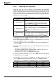
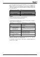
The current warning mask can be read via parameter
Actual Appl. Warning Mask
627. The operation modes of parameter Create Appl. Warning Mask 626 are en-
coded in
Actual Appl. Warning Mask 627. If several warnings are combined, the
code can be calculated from the hexadecimal addition of the individual warnings and
the corresponding code.
Warning code
Create Warning Mask Application 626
A FFFF - 2 - Activate all Warnings
A 0002 SW-LIM CW 11 - Warning pos. SW limit switch
A 0004 SW-LIM CCW 12 - Warning neg. SW limit switch
A 0008 HW-LIM CW 13 - Warning pos. HW limit switch
A 0010 HW-LIM CCW 14 - Warning neg. HW limit switch
A 0020 CONT 15 - Warning position controller
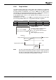
Example:
Warning codes A0002 SW-LIM CW + A0004 SW-LIM CCW
= Warning code A0006 SW-LIM CW SW-LIM CCW
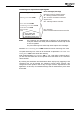
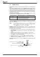
The individual warning messages and the configured warning mask are available as
operation modes for the digital outputs:
Digital signal Function
26 - Application Warning All warnings application are deactivated.
27 - Warning Mask, Application
All warnings of Warning Mask, Application
are activated.
28 -
Warning, gen. +
Warning, Application
All warnings and application warnings are
deactivated.
29 -
Warn. Mask, gen. +
Warn. Mask, Appl.
All warnings of warning mask and all warn-
ings of application warning mask are acti-
vated.
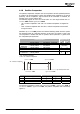
126 - Inv. Warning Application Operation mode 26 inverted
127 -
Inv. Warning Mask Applica-
tion
Operation mode 27 inverted
128 -
Inv. Warning, gen. +
Warning, Application
Operation mode 28 inverted
129 -
Inv. Warn. Mask, gen +
Warn.
Operation mode 29 inverted
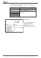
Additionally, logic signals "215 – Application Warning Mask" and "216 – Application
Warning" can be used as sources for logic functions.
If an application warning is present, "A8000 Warn2" is displayed additionally via
parameter
Warnings 269.
Application manual Positioning 10304/08