
Operating instructions

04/08 Application manual Positioning 107
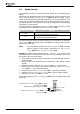
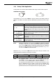
4.11 Rotary Table Application
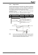
A rotary table is a round axis with unlimited travel range. No limit switch required.
Unlimited travel ranges.
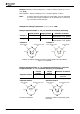
Via parameter
Operation Mode 1240, the type of motion to the target position is
defined. The direction of rotation and way optimization (shortest way) can be speci-
fied.
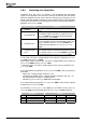
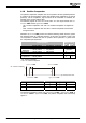
Operation mode 1240
Function
0 - Off Round table positioning switched off.
1 - On
Round table positioning switched on.
Direction of rotation depends on parameterized target po-
sition. Motion is always performed such that 0° will not be
passed. Maximum travel range is always smaller than one
rotation.
2 -
On / Optimized
(shortest way)
Shortest way to target position is taken.
Relative motions are not optimized; motion blocks must be
configured accordingly.
3 -
On / Clockwise
Rotation
Motion is performed in clockwise (positive) direction (abso-
lute positioning). Negative direction is disabled for absolute
positioning.
4 -
On / Anticlock-
wise Rotation
Motion is performed in anticlockwise (negative) direction
(absolute positioning). Positive direction is disabled for
absolute positioning.
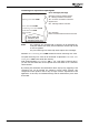
Note:
Settings of parameter
Operation Mode 1240 only affect the direction
of rotation in the case of absolute positioning operations (parameter
Motion Mode 1208). Relative positioning operations are not optimized;
direction of rotation depends on the settings of parameter
Target Posi-
tion/Distance
1202 in the motion blocks.
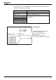
Parameter
Units per Revolution 1241 must be set to the units per revolution. This
setting represents the distance covered per revolution.
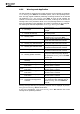
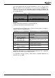
Parameter Setting
No. Description Min. Max. Fact. sett.
1241 Units Per Revolution 1 u 2
31
-1 u 65 536 u
Note:
The reference system must be set up via parameters
Feed Con-
stant
1115, Gear Box: Driving shaft revolutions 1116 and Gear Box:
Motor shaft revolutions
1117 (Chapter "Reference system").
Use exact gear transmission factors. The exact gear transmission factor
can be calculated from the number of teeth of the individual gear-
wheels. Do not use rounded values, because this may result in a drift
(deviation between the actual position and the required position).
Application manual Positioning 10704/08