
Operating instructions


114 Application manual Positioning 04/08
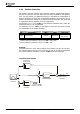
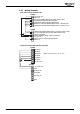
In configuration 240 S4IND (X210A.6) and S5IND (X210A.7) are parameterized by
default as inputs for Encoder 1. Via S6IND (X210B.1), the zero track of a HTL en-
coder can be evaluated. Alternatively, the inputs of an optional extension module EM-
ENC can be used as encoder inputs. In this case, inputs S4IND and S5IND must be
parameterized for a changed assignment of functions.
In configuration 540, evaluation of Encoder 1 (parameter
Operation Mode 490) is
disabled by default, parameter
Act. Speed Source 766 is not available. Digital inputs
S4IND (X210A.6) and S5IND (X210A.7) can be used as inputs for HW limit switches.
Configuration 540 enables evaluation of resolvers and requires an optional expansion
module EM-RES.
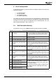
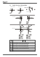
Parameters for inputs:
Parameter Setting/Selection
30 Configuration 240 440, 540
490 Operation Mode
speed sensor 1
1 … 1132 0 - Off
766 Act. Speed Source 1 - Speed sensor 1 or
2 - Speed sensor 2
1)
2)
1222 Start Positioning 71 - S2IND
1232 Jog Clockwise 71 - S2IND
1
1223 Stop Positionierung 72 - S3IND
1233 Jog Anticlockwise 72 - S3IND
2
Fact. set. Setting
1138 Positive HW Limit Switch 7 - Off 7 - Off e.g. 540
1137 Negative HW Limit Switch 7 - Off 7 - Off e.g. 541
1139 Home Switch 75 - S6IND
1239 Teach-In-Signal 76 - MFI1D
1231 Jog-Mode Active 76 - MFI1D
3
1)
Only available in combination with extension module, e.g. EM-ENC/EM-RES.
2)
Configuration 540 requires an extension module EM-RES for evaluation of the resolver on
the synchronous motor, is wired to this source internally and cannot be changed. Configuration
440 uses internal operands.
1
Digital input S2IND has function "JOG Clockwise":
−
If HIGH signal is present on MFI1D. MFI1D is assigned to parameter
Jog-Mode
Active
1231 (factory settings).
− Automatically by setting parameter
Operation Mode 1221 to:
"301 - Teach-In, Motion Block Sel. via Digital Inputs" or
"302 - Teach-In, Motion Block Sel. via P. 1228".
2
Digital input S3IND has function "JOG Anticlockwise":
−
If HIGH signal is present on MFI1D. MFI1D is assigned to parameter
Jog-Mode
Active
1231 (factory settings).
− Automatically by setting parameter
Operation Mode 1221 to:
"301 - Teach-In, Motion Block Sel. via Digital Inputs" or
"302 - Teach-In, Motion Block Sel. via P. 1228".
3
JOG mode is switched on automatically by setting parameter Operation Mode
1221 to:
− "301 - Teach-In, Motion Block Sel. via Digital Inputs" or
− "302 - Teach-In, Motion Block Sel. via P. 1228".
Digital input MFI1D is provided for connection of a teach-in signal in these settings
(for saving current position as target position in motion block). In these settings, JOG
mode does not have to be switched on separately via digital input MFI1D (parameter
Jog-Mode Active 1231).
For all other settings of parameter
Operation Mode 1221, digital input MFI1D is
provided for activation of JOG mode.
Application manual Positioning 04/08114