
Operating instructions


04/08 Application manual Positioning 23
18
245
0.18
2.45
G ===
1117
1116
srevolution shaft Motor:Box Gear
srevolution shaftDriving :Box Gear
Factorear
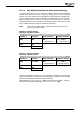
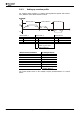
Set Gear Box: Driving shaft revolutions 1116 to 245.
Set
Gear Box: Motor shaft revolutions1117 to 18.
[]
()
[
]
U 009446200563160units 9996316051
18
U
Ink
2
245
U
u
3600Ink 12
us
16
31
max
±≈ °±≈±=
⋅
⋅⋅ − ±
=
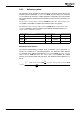
Note:
Gear transmission factors are rounded in many cases and may result in
a "drift" in the application, i.e. due to the rounded values, the deviation
between the actual position and the required position increases with
each revolution. This particularly affects rotary table applications which
turn in one direction continuously because their position change con-
tinues to increase all the time. Use exact gear transmission factors in
order to eliminate this drift. The exact gear transmission factor can be
calculated from the number of teeth of the individual gearwheels.
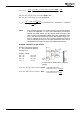
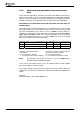
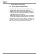
Example: Calculation of gear factors
Example: Three-stage gearbox
(i = 67.7 rounded) at reduction
gearing of 3:1.
Number of teeth:
D1 = 13
D3 = 12
D5 = 11
V1 = 1
D2 = 25
D4 = 27
D6 = 31
V2 = 3
D1
D2
D3
D4
D5
D6
M
A
V2
V1
M: motor side, A: output side, V: reduction
gearing
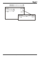
Gear Box: Driving shaft revolutions 1116
= D2 x D4 x D6 x V2
= 25 x 27 x 31 x 3 = 62775
Gear Box: Motor shaft revolutions 1117
= D1 x D3 x D5 x V1
= 13 x 12 x 11 x 1 = 1716
Application manual Positioning 2304/08