
Operating instructions


04/08 Application manual Positioning 29
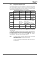
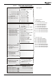
4.1.1 Assignment of digital inputs
In the individual operation modes of the positioning, the digital inputs have different
inputs. The following table provides an overview of the functions and assigns them
to the terminals, as parameterized in the factory settings for the functions. Assign-
ment of terminals S4IND/S5IND depends on
Configuration 30.
Function
Positioning JOG mode Homing Teach-In
Opera-
tion mode
1221 =
1xx, 2xx 1xx, 2xx 1xx, 2xx 30x
Terminal
S2IND
Start Positioning
1222
Jog Clockwise
1232
Start Positioning
1222
Jog Clock-
wise
1232
S3IND
Stop Positioning
1223
Touch probe
1)
Jog Anticlock-
wise
1233
"0"
Jog Anti-
clockwise
1233
S4IND
30 = 440, 540
30 = 240
Free programmable, e.g. for
Positive HW Limit Switch 1138
2)
Encoder track A
S5IND
30 = 440, 540
30 = 240
Free programmable, e.g. for
Negative HW Limit Switch 1137
2)
Encoder track B
S6IND
Home Switch
1139
MFI1D
"0" "1"
Teach-In
Signal
1239
1)
Deactivate function "Stop Positioning" at S3IND if "Touch Probe" mode is used in
the motion sequence. For parameter
Stop Positioning 1223, you can also select any
other digital input.
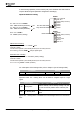
2)
Assign S4IND and S5IND to the inputs for HW limit switches. Parameterized func-
tions will be evaluated only if the inputs are not used as encoder inputs.
For evaluation as break contacts, you can assign inverted inputs to the parameters
for the HW limit switches, e.g.
Positive HW Limit Switch 1138 = "540 - S4IND in-
verted (Hardware)". This can be used for wire-break monitoring.
Note:
For controller release of the power component, wiring of the following
digital inputs is required:
STOA (terminal X210A.3) and STOB (terminal X210B.2).
In safety-oriented systems, the documentation "Safe Torque Off" shall
be complied with.
Application manual Positioning 2904/08