
Operating instructions


04/08 Application manual Positioning 35
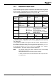
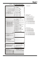
4.2.2 Input and output signals for homing
Terminal assignment for homing
Function
Con-
troller
release
Start
Homing
(manual)
1235
1)
Stop
Positio-
ning
1223
Home
Switch
1139
2)
Neg. HW
Limit
Switch
1137
Pos. HW
Limit
Switch
1138
Off* S3IND* S6IND *
6)
S5IND
6)
S4IND
6)
Drive disabled 0 X X X 0
(1)
0
(1)
Homing is
started
1 1 0 0 0
(1)
0
(1)
Home position
is set
1 1 0 edge
3)
0
(1)
0
(1)
Homing is
interrupted
1 1 1 X 0
(1)
0
(1)
Error message, limit switch as make contact function
(brake contact function)
F1445
5)
X X X X 1
(0)
1
(0)
F1447
(F1446)
5)
X X X X 0
(1)
1
(0)
4)
F1448
(F1446)
5)
X X X X 1
(0)
4)
0
(1)
0 = Low / 1 = High / X = any / * = factory setting
1)
Start Homing: Homing is started automatically if required (drive not yet refer-
enced) in parameter configuration
Operation Mode 1220 = "2 – automatic". In
parameter configuration
Operation Mode 1220 = "1 – manual", the digital signal
Start Homing (manual) 1235 must be present.
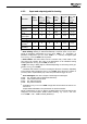
2)
Home switch: The home switch can be a reference cam, a limit switch or the
zero pulse of an encoder. Also refer to the descriptions of the individual homing
modes (parameter
Homing Mode 1130) in section 5.
3)
Edge: The rising or falling edge is evaluated depending on the homing mode (pa-
rameter
Homing Mode 1130).
4)
A hardware limit switch is used for reversing the direction of rotation, depending
on the homing mode (parameter
Homing Mode 1130). If the direction of rotation is
reversed, value 0 is permissible (only in this case) and will not trigger an error.
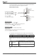
5)
Error messages: Also refer to chapter “Positioning Error Messages"
F1445: Pos. and Neg. HW-Lim Switch Simultaneously
F1446: Limit Switch Incorrect Wired
F1447: Pos. HW Limit Switch
F1448: Neg. HW Limit Switch
6)
Dependent on Operation Mode 490. Comply with the instructions in sections 3.4
and 3.5.1.4.
Assign S4IND and S5IND to the parameters for HW limit switches.
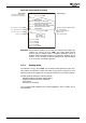
Values in parentheses
(0)
and
(1)
apply if the digital inputs for the limit switches are
configured as inverted inputs
(brake contact function)
, e.g. Positive HW Limit
Switch
1138 = "540 - S4IND inverted (Hardware)".
Application manual Positioning 3504/08