
Operating instructions


36 Application manual Positioning 04/08
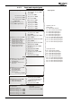
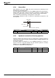
In most homing operations, a home switch (cam) and a hardware limit switch will be
required. Mind wiring and parameter configuration accordingly.
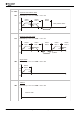
Input terminals for homing
1
2
3
4
5
6
7
X21
0
A
+20 V/180 mA
GND 20 V
STOA (safety function)
S2IND
Pos. HW Limit Switch
Manual start of homing
Automatic start of homing
S3IND
S4IND
S5IND
Neg. HW Limit Switch
P
os. HW Limit Switch
=
"540 - S4IND inverted (Hardware)"
1138
N
eg. HW Limit Switch
=
"541 - S5IND inverted (Hardware)"
1137
STOB (safety function)
S1OUT
MFO1A
+10 V/4 mA
MFI1D
GND 10 V
S6IND
X210B
1
2
3
4
5
6
7
Home Switch
Home Switch
=
"75 - S6IND" (factory setting)
1139
Start Homing (manual)
1235
Operation Mode
= "1 - manual"
1220
Assign digital signal
Operation Mode
= "2 - automatic"
1220
(factory setting)
Start Positioning
= S2IND (X210A.4)
1222
Controller release:
Connect STOA (X210A.3) and STOB (X210B.2) for the safety function
Controller release:
Connect STOA (X210A.3) and STOB (X210B.2) for the safety function
set
set
set
For a description of the homing modes, refer to chapter 5 (List of homing modes).
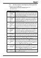
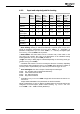
Parameter Settings
No. Description Min. Max. Fact. sett.
1130 Homing Mode 0 35 0
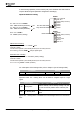
Operation mode "59 – Homing Done" can be linked to a digital output or a logic
signal.
Digital signal Function
59 - Homing Done
Output signal if reference position is set (reference
position defined
). This is done by homing or by tak-
ing over the current position as the reference posi-
tion.
159 - Inv. Homing Done
Like operation mode 59, but with inverted output
signal.
Signal "614 – Homing Done" is available as an internal signal source for control func-
tions.
Application manual Positioning 04/0836