
Technical data


29
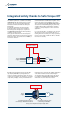
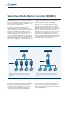
Functional layout
The terminals, connectors and push-buttons of the
Agile user interface are located where they are
easily accessible without having to use tools.
The power terminals (inverter power input and
motor power output) are located at the top and
bottom of the drive and are individually marked
with clearly visible symbols to ensure correct
wiring.
Control terminals are located at the front of the
unit and are easily accessible simply by removing
the blue push-on protective cover.
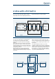
A keypad, elegantly integrated in the drive body,
provides six function keys for drive programming,
monitoring and control.
The drive is also equipped with an RJ45 connector
fortheRS485Modbusserialinterfaceaswell
VABusandaslotforanMMCmemorycardthat
can be used to copy drive parameters.
An RS232 port, Profibus DP or CANopen
communication port can be fitted as optionals. If
one or more of these ports is required, installation
is quick and easy and only requires the protective
cover to be removed to access the slots beneath
the operator panel in the front of the drive. The
installation of these optional modules does not
alter the overall dimensions of the drive.
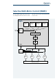
Removable top
front cover
Removable bottom
front cover
Display
Input power terminals
DC bus connector
Heat sink
Name plate
Connection screens plate
Terminals for motor power
output and braking resistance
Control terminals
Slot for memory card
RJ45 connector for
RS485 communications
DB9 connector
Optional
communication
modules
Integrated keypad