
Operating instructions

08/06 11
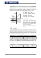
4.1.3 Characteristic
The mapping of the analog input signals onto a frequency or percentage reference
value is possible for various demands. The parameterization is to be done via two
points of the linear characteristic of the reference channel.
T
he characteristic point 1, with the coordinates X1 and Y1, and the characteristic point
2, with the coordinates X2 and Y2, can be set in four parameters.
T
he characteristic points X1 and X2 are stated as percenta
g
es, as the analo
g
input can
be switched as a current or voltage input via switch S3.
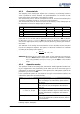
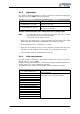
Parameter Setting
No. Description Min. Max. Fact. sett.
564 Characteristic point X1 -100.00 % 100.00 % -98.00 %
565 Characteristic point Y1 -100.00 % 100.00 % -100.00 %
566 Characteristic point X2 -100.00 % 100.00 % 98.00 %
567 Characteristic point Y2 -100.00 % 100.00 % 100.00 %
The coordinates of the characteristic points are related as a percenta
g
e to the analo
g
signal, with 10 V or 20 mA, and the parameter Maximum Frequency 419 or parame-
ter
Maximum reference percentage 519. The chan
g
e of direction of rotation can be
done via the digital inputs of the frequency inverter and/or by selecting the character-
istic points.
The definition of the analog input characteristic can be calculated via the two-poin
t
form of the straight-line equation. The speed Y of the drive mechanism is controlled
according to the analog control signal X.
()
Y1X1X
X1-X2
Y1-Y2
Y +−⋅=
Attention!
Monitoring of the analog input signal via the parameter
E
rror/Warnin
g
Behavior 563 demands a check of the characteristic parameters. Sensible
use is only possible if the
Characteristic point X1 564 is in the positive
range.
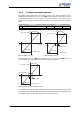
4.1.4 Operation modes
The operation modes of the analog input characteristic enable application-related scal-
in
g
as a supplement to the characteristic points stated. One of the four linear types o
f
characteristic is selected for adaptation of the si
g
nal for the analo
g
input si
g
nal via the
parameter
Operation mode 562.
If the characteristic points are not suited for the type of characteristic selected, the
characteristic points are corrected internally.
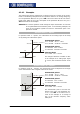
Operation mode Function
1 - bipolar The analog input signal is mapped onto the reference
figure according to the characteristic points (X1/Y1)
and (X2/Y2).
11 - unipolar With a negative parameter value of the characteristic
points X1 or X2, they are mapped to the reference
value zero.
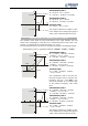
21 - unipolar
2…10 V / 4…20 mA
If the characteristic points X1 or X2 have been set
with a negative parameter figure or smaller than 0%,
the input characteristic is mapped to the reference
value 20%.
101 - bipolar absolute value Negative parameter values of the characteristic points
Y1 or Y2 are mapped as a positive reference value in
the characteristic.
Further information on the operation modes stated in the table can be found in the
following chapter "Examples“.