
Operating instructions

18 08/06
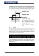
4.2 Resolver input EM-RES
The resolver input is used for evaluating the position information from the resolver.
The frequency of the field signal for the resolver can be selected via parameter Opera-
tion Mode
380.
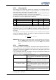
Operation mode Function
5- frequency 5 kHz
10- frequency 10 kHz
20- frequency 20 kHz
Frequency of the reference signal for the resolver
If the no. of resolver pole pairs > 1, the measured electric an
g
le runs throu
g
h the
range of 0°...360° several times during one mechanical revolution.
For the detection of the position an
g
le of the rotor at a synchronous motor, the ratio
of the no. of motor pole pairs to the no. of resolver pole pairs must be an integer.
The no. of pole pairs of the resolver can be adjusted via parameter
N
o. of Pole Pairs
381.
Parameter Function
No. Description Min. Max. Fact. sett.
381 No. of pole pairs 1 24 1
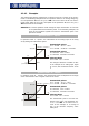
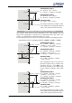
Assignment of the socket:
Resolver field signal EM-RES (X410A.1): REF+
Resolver field signal EM-RES (X410A.2): REF-
Resolver input EM-RES (X410A.3): SIN-
Resolver input EM-RES (X410A.4): SIN+
Resolver input EM-RES (X410A.5): COS-
Resolver input EM-RES (X410A.6): COS+
4.2.1 Offset
In order to enable the start of a synchronous machine, the absolute position of the
rotor must be known. This information is required in order to actuate the stator wind-
ings in the right order depending on the position of the rotor. The position of the ro-
tary field in the synchronous machine must be controlled in order to obtain a continu-
ous movement of the rotor. During first commissioning, the position of the rotor wind-
ing of the resolver is adjusted to the rotor displacement angle of the synchronous mo-
tor by ad
j
ustin
g
the offset. For operatin
g
a synchronous machine with resolver, the
offset must be adjusted in order to obtain perfectly true runnin
g
and a maximum
torque.
The correct
Offset 382 is adjusted when the flux-forming voltage 235 reaches the
value 0 (approximately) while the motor is turning.
Parameter Function
No. Description Min. Max. Fact. sett.
382 Offset -360.0° 360.0° 0.0°
The offset can be determined and adjusted as follows:
• Durin
g
first commissionin
g
"SEtUP" will be displayed in the control unit. Press ESC
to stop this operation. The guided commissioning („SETUP“) is performed after ad-
justing the offset.
• Open the parameter menu "PARA" and enter the machine data indicated on the
type plate or the data sheet of the motor.