
Operating instructions

20 08/06
Depending on the behavior of the motor after start, carry out the following steps:
−
Motor does not turn, or the motor shaft only turns to a new position and
stops again:
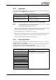
• Check if the parameters No. of Pole Pairs 373 for the motor and
N
o. of Pole
Pairs
381 for the resolver are set correctly.
If these values are ad
j
usted correctly, take the followin
g
measures complyin
g
with
the safety instructions.
Warning! The mains, direct voltage and motor sockets can be live with dangerous
volta
g
e after disconnection of the frequency inverter. Work only on the
device after a waitin
g
period of some minutes until the DC link capacitors
have discharged.
• Before electrical installation work, de-ener
g
ize the frequency inverter and take
appropriate precautions to make sure it is not re-ener
g
ized unintentionally.
Make sure that the frequency inverter is de-energized.
• Exchange two motor phases (e.g. U and V) at the frequency inverter sockets
because the senses of rotation of the motor and the resolver do not corre-
spond to each other.
• Switch on the power supply again.
• As described above, adjust a low speed reference value and start the motor.
If the motor does not start despite the phase exchange:
• Increase the parameter value for Offset 382 by 90°, divided by the no. of mo-
tor pole pairs.
If the motor still does not turn, exchan
g
e the two motor phases (e.
g
. U and V)
again.
− The motor turns and accelerates until it reaches the Frequency Switch-Of
f
Limit 417:
• Check the resolver lines and check the resolver connection contacts.
• In the case of fault messa
g
e "Overfrequency" F1100: increase the paramete
r
value for Offset 382 by 180°, divided by the no. of motor pole pairs.
− If the motor turns at the ad
j
usted speed and in the ri
g
ht direction, carr
y
out the fine adjustment of the offset:
• Adjust the parameter value for Offset 382 in small steps (e.
g
. 2.5°) until the
flux-forming voltage 235 is approximately 0.
− In case the flux-formin
g
volta
g
e deviates from 0 si
g
nificantly, ad
j
ust the offse
t
in bigger steps.
− In the case of a positive flux-forming voltage, increase the offset.
− In the case of a negative flux-forming voltage, reduce the offset.
• Adjust parameters Frequency Switch-Off Limit 417 and Current Limit 728 to
the required values.
• Repeat the fine adjustment of the offset at 50% of the rated frequency.
This completes the offset adjustment.
• Start the guided commissioning. This is required for optimum current control.