
Operating instructions


08/06 21
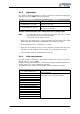
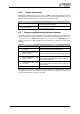
4.2.2 Actual speed source
Switch-over is effected via Actual Speed Source
766. If the resolver delivers the actual
value signal for the speed controller, speed sensor 2 must be selected as the source In
the basic setting, speed sensor 1 is used as the actual value source.
Operation mode Function
1 - Speed sensor 1
The actual speed source is speed sensor 1 of the
basic device (factory setting).
2 - Speed sensor 2
The actual speed source is speed sensor 2 of the EM-
RES-02 expansion module.
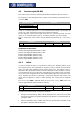
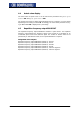
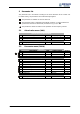
4.3 Frequency and percentage reference channel
T
he varied functions for the specification of the reference values are connected in the
various configurations by the frequency or percentage reference channel. The
Refer-
ence frequency source
475, and the Reference percentage source 476 determine the
additive connection of the available reference sources as a function of the installed
hardware.
Operation mode Function
2 - EM-S1INA, absolute value Reference source is the analog input EM-S1INA
4 -
MFI1A + EM-S1INA, abso-
lute value
Reference sources are the multifunctional input
MFI1A and the analog input EM-S1INA
14 -
MFI1A + EM-S1INA + FF,
absolute value
Reference sources are the multifunctional input
MFI1A, analog input EM-S1INA and fixed frequency
FF
24 -
MFI1A + EM-S1INA + MP,
absolute value
Reference sources are the multifunctional input
MFI1A, analog input EM-S1INA and the motor po-
tentiometer function MP
34 -
speed sensor 2 (F2), abso-
lute value
The frequency signals of the resolver are evaluated
using a fixed number of division marks of 1024 as a
reference value.
102 to 124 Operation modes with signs (+/-)
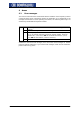
Additional to the operation modes listed, those stated in the operatin
g
instructions o
f
the frequency inverter in the chapter "Frequency reference channel“, and in the chap-
ter "Percentage reference channel“ also apply.