
Operating instructions

08/06 25
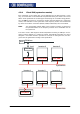
If a PC or a PLC is used as a master, the identifiers of the Rx/Tx-SDO1 can be
adapted by parameterization on the frequency inverter.
Attention! In free assignment of identifiers, there may not be any double occu-
pancy.
The identifier range 129...191 may not be used as the emergency tele-
grams can be found there.
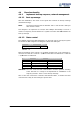
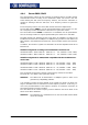
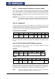
The setting of the identifiers of the RxSDO1 is done via the parameter
RxSDO1-
Identifier
921.
Parameter Setting
No. Description Min. Max. Fact. sett.
921 RxSDO1-Identifier 0 2047 0
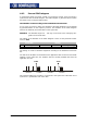
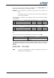
The setting of the identifiers of the TxSDO1 is done via parameter number 922.
Parameter Setting
No. Description Min. Max. Fact. sett.
922 TxSDO1-Identifier 0 2047 0
T
he settin
g
"0” results in identifier assi
g
nment accordin
g
to the Predefined Connection
Set.
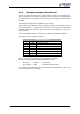
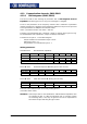
The second SDO channel can be deactivated via the
SDO2 Set Active 923.
Operation mode Function
0 -SDO2 deactivated Communication channel deactivated
1 -SDO2 activated Communication channel activated for the visuali-
zation tool
The identifier assignment for the second SDO channel is always to the speci-
fication:
Identifier Rx-SDO2 = 1600 + Node-ID
Identifier Tx-SDO2 = 1472 + Node-ID
Note: In this way, firm identifiers via which communication takes place are
available for the visualization tool.