
Operating instructions

40 08/06
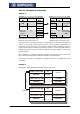
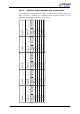
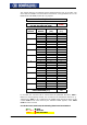
4.11.5.3 Examples of virtual links
Example 1:
Frequency inverter 1 Frequency inverter 2
Source
- No.
Input link TxPDO1
Byte
RxPDO1
Byte
Source
- No.
Target
0 0 Control word
740
950
1
1
704 Control input,
Control word
99
2 2
3 3
4 4
5 5
6 6
Output ref-
erence fre-
quency
channel 62
955
7
7
709 Ramp input,
Line set value
137
Parameter 950 = Source-No. 740 Parameter 99 = Source-No. 704
Parameter 955 = Source-No. 62 Parameter 137 = Source-No. 709
T
he control word of frequency inverter 1 is linked with the control word of frequency
inverter 2. In this way, both frequency inverters can be operated synchronously via
the remote control. The output of the reference value channel of frequency inverter 1
is laid onto the output of the ramp of frequency inverter 2. In this way, both frequency
inverters have a joint source of reference values and are given reference values in the
internal notation.
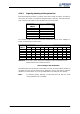
As an extension, a number of frequency inverters can also exist on the receive side
(Rx), these then being supplied with data parallel and simultaneously.
The input link not used in the TxPDO1 of frequency inverter 1 is on ZERO and is thus
not served.
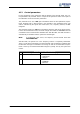
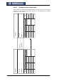
Example 2:
Example of a virtual link with transmission via the system bus:
TxPDO1 Boolean1
946
Parameter
Identifier
385
Source-No.
71-S2IND
system bus
TxPDO1 Identifier
925
Inverter 1
Start-clockwise
068
Parameter
Identifier
385
Source-No.
700-RxPDO1 Boolean
Parameter
Parameter
RxPDO1 Identifier
924
Inverter 2