
Operating instructions

42 08/06
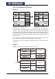
4.13 Handling of the parameters of the system bus
As soon as the system bus expansion module EM-SYS exists in an frequency inverter,
the actual value parameters for system state and bus state are activated and can be
observed in the actual value menu VAL of the control unit KP500 or with the VPlus PC
program in the menu Actual values \ Systembus.
Note: The actual value parameters are on control level 3 and are thus available
for the user at any time.
All the setting parameters for the configuration of the system bus are not directly ac-
cessible for the user. For defined customer applications, pre-defined XPI files can be
generated by VECTRON for the VPlus PC program, with which the necessary parame-
ters are visible for the user. The application-relevant variables are then available in
these XPI files.
Note: XPI files can be read in addition to the loaded parameter information o
f
the frequency inverter into the VPlus PC program.
In the menu of the software under the point "Edit" you find the com-
mand "Read in XPI file".
The method of working via an XPI file has its reasoning in the fact that deep interven-
tions in the system are possible via the system bus and can lead to serious problems
in the application with an untrained user. Via the XPI files, a user is
g
iven a selection
list pre-defined by VECTRON.
Attention!
T
he confi
g
uration of the necessary parameters for the system bus is
accessible by a XPI file with the help of the VPlus PC program.
The control unit KP500 does not support this functionality.
If the expansion module system bus EM-SYS is installed additionally to a
communication module for the field bus connection (CM-232, CM-485 o
r
CM-PDP) in the frequency inverter, the parameterization can be made
with the interface adapter KP232.
Experienced users have complete access to all the existin
g
sources and possible input
links with the XPI file of the active functions. The selection depends on the selected
configuration and control procedure.
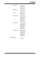
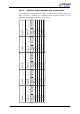
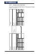
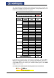
T
he display of the parameters when usin
g
the XPI file is accordin
g
to the followin
g
structure:
System bus
Basic Settings 900Node-ID
903Baud-Rate
Master Functions 904Boot-Up Delay
919SYNC-Time
SYNC-Identifier 918SYNC-Identifier
SDO1-Identifier 921RxSDO1-Identifier
922TxSDO1-Identifier
SDO2 Set Active 923SDO2 Set Active
PDO-Identifier 924RxPDO1-Identifier
925TxPDO1-Identifier
926RxPDO2-Identifier
927TxPDO2-Identifier
928RxPDO3-Identifier
929TxPDO3-Identifier