
Operating instructions

50 08/06
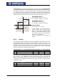
5.1.3 Characteristic
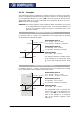
The mapping of the analog input signals onto a frequency or percentage reference
value is possible for various demands. The parameterization is to be done via two
points of the linear characteristic of the reference channel.
T
he characteristic point 1, with the coordinates X1 and Y1, and the characteristic point
2, with the coordinates X2 and Y2, can be set in four parameters.
T
he characteristic points X1 and X2 are stated as percenta
g
es, as the analo
g
input can
be switched as a current or voltage input via switch S3.
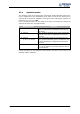
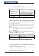
Parameter Setting
No. Description Min. Max. Fact. sett.
564 Characteristic point X1 -100.00 % 100.00 % -98.00 %
565 Characteristic point Y1 -100.00 % 100.00 % -100.00 %
566 Characteristic point X2 -100.00 % 100.00 % 98.00 %
567 Characteristic point Y2 -100.00 % 100.00 % 100.00 %
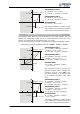
The coordinates of the characteristic points are related as a percenta
g
e to the analo
g
signal, with 10 V or 20 mA, and the parameter Maximum Frequency 419 or parame-
ter
Maximum reference percentage 519. The chan
g
e of direction of rotation can be
done via the digital inputs of the frequency inverter and/or by selecting the character-
istic points.
The definition of the analog input characteristic can be calculated via the two-poin
t
form of the straight-line equation. The speed Y of the drive mechanism is controlled
according to the analog control signal X.
()
Y1X1X
X1-X2
Y1-Y2
Y +−⋅=
Attention!
Monitoring of the analog input signal via the parameter
E
rror/Warnin
g
Behavior 563 demands a check of the characteristic parameters. Sensible
use is only possible if the
Characteristic point X1 564 is in the positive
range.