
Operating instructions

52 08/06
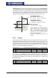
5.1.4.1 Examples
The analog input signal is mapped onto a reference value as a function of the charac-
teristic. The following examples show the operation modes for an analog voltage sig-
nal. The parameter
Minimum Frequency 418 is set to the value 0.00 Hz. The charac-
teristic point 100% for the Y-axis corresponds to the parameter
Maximum Frequency
419 of 50.00 Hz in the examples.
Attention!
T
he various operation modes chan
g
e the input characteristic as a function
of the parameterized characteristic points. In the followin
g
examples, the
areas of the coordinate system from which a characteristic point is dis-
placed are marked.
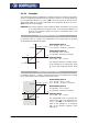
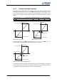
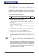
Operation mode "1 – bipolar"
In operation mode "1 – bipolar“, the characteristic of the analo
g
input can be freely
set by stating two characteristic points.
Characteristic point 1:
X1 = -70.00% · 10 V = -7.00 V
Y1 = -50.00% · 50.00 Hz = -25.00 Hz
Characteristic point 2:
X2 = 80.00% · 10 V = 8.00 V
Y2 = 85.00% · 50.00 Hz = 42.50 Hz
Tolerance band:
ΔX = 2.00% · 10 V = 0.20 V
(X2=80% / Y2=85%)
8V
Y
X
-25Hz
42.50Hz
(X1=-70% / Y1=-50%)
-7V
T
he chan
g
e of direction of rotation is done
in the example at an analo
g
input si
g
nal
of -1.44 V, with a tolerance band of ±0.20
V.
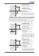
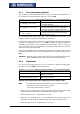
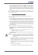
Operation mode "11 – unipolar"
In operation mode "11 – unipolar“, the characteristic points are displaced to the ori
g
in
of the characteristics with a negative value for the X-axis.
Characteristic point 1:
X1 = -70.00% · 10 V = -7.00 V
Y1 = -50.00% · 50.00 Hz = -25.00 Hz
Characteristic point 2:
X2 = 80.00% · 10 V = 8.00 V
Y2 = 85.00% · 50.00 Hz = 42.50 Hz
Tolerance band:
ΔX = 2.00% · 10 V = 0.20 V
(X2=80% / Y2=85%)
8V
Y
X
-25Hz
42.50Hz
(X1=-70% / Y1=-50%)
-7V
The characteristic point 1 has been dis-
placed to the origin. The parameter
Tol-
erance band
560 is not taken into ac-
count in this example, as no chan
g
e o
f
sign of the reference frequency value
takes place.