
Operating instructions

56 08/06
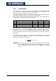
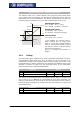
5.1.7 Error and warning behavior
The monitoring of the analog input signal necessary accordin
g
to the application is to
be configured via the parameter
Error/Warning behavior 563.
Operation mode Function
0 -Off The input signal is not monitored.
1 -Warning < 1 V / 2 mA
If the input signal is less than 1 V or 2 mA, there
is a warning message.
2 -Shutdown < 1 V / 2 mA
If the input signal is less than 1 V or 2 mA, there
is a warning message, the drive mechanism is
decelerated according to stopping behavior 1.
3 -
Fault switch-off
< 1 V / 2 mA
If the input signal is less than 1 V or 2 mA, there
is a warning and fault message and the drive
mechanism stops freely.
T
he monitorin
g
of the analo
g
input si
g
nal is active independent of the release of the
frequency inverter according to the operation mode selected.
In operation mode 2, the drive mechanism is decelerated independent of the stoppin
g
behavior set (Parameter Operation mode 630) accordin
g
to stoppin
g
behavior 1
(shutdown and switch-off). If the set holding time has expired, there is a fault mes-
sage. A repeat start of the drive mechanism is possible by switchin
g
the start si
g
nal on
and off if the fault has been cleared.
Operation mode 3 defines the free stoppa
g
e of the drive mechanism, independent o
f
the stopping behavior selected, which is stipulated with the parameter Stop function
630.
Attention!
Monitoring of the analog input signal via the parameter
E
rror/Warnin
g
Behavior
563 demands a check of the characteristic parameters.
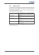
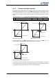
5.1.8 Adjustment
As a result of component tolerances, it can be necessary to ad
j
ust the analo
g
input.
Parameter
Adjustment 568 is used for this purpose.
Operation mode Function
0 -no adjustment Normal operation
1 -Adjustment 0 V / 0 mA
Adjustment of the measurement with an analog
signal of 0 V or 0 mA.
2 -Adjustment 10 V / 20 mA
Adjustment of the measurement with an analog
signal of 10 V or 20 mA.
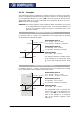
Example of the adjustment of the analog input with a voltage signal:
Note: The measurements for the adjustment are to be done with a suitable
measuring instrument and the correct polarity.
If not, faulty measurements can result.
• Apply 0 V to the analo
g
input; e.
g
. with a wired link from the socket of the analo
g
input X410B.4 to socket X210B.7 (earth/GND) of the frequency inverter.
• Select operation mode "1 - Adjustment 0 V / 0 mA“.
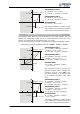
• Apply 10 V to the analog input, e.g. with a wired link from the socket of the ana-
log input to socket X210B.5 (reference output 10 V) of the frequency inverter.
• Select operation mode "2 - Adjustment 10 V / 20 mA“.